- 您现在的位置:买卖IC网 > PDF目录141434 > W7NCF256H31IS9JG (WHITE ELECTRONIC DESIGNS CORP) 16M X 16 FLASH 3.3V PROM CARD, 150 ns, UUC PDF资料下载
参数资料
| 型号: | W7NCF256H31IS9JG |
| 厂商: | WHITE ELECTRONIC DESIGNS CORP |
| 元件分类: | PROM |
| 英文描述: | 16M X 16 FLASH 3.3V PROM CARD, 150 ns, UUC |
| 封装: | CARD |
| 文件页数: | 12/13页 |
| 文件大小: | 172K |
| 代理商: | W7NCF256H31IS9JG |
March 2007
Rev. 10
W7NCFxxx-H Series
8
White Electronic Designs Corporation (602) 437-1520 www.whiteedc.com
White Electronic Designs
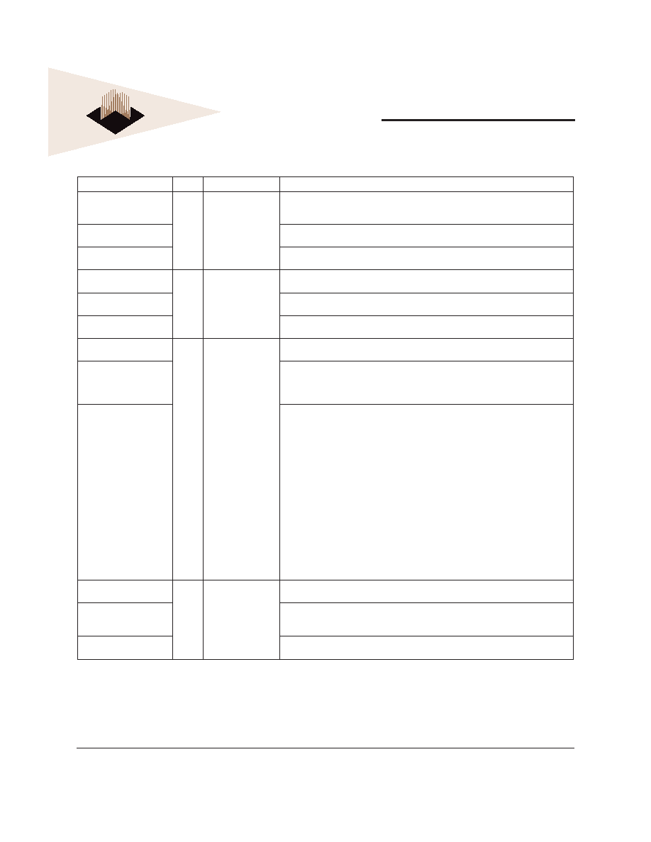
Signal Name
Dir.
Pin
Description
D15 - D00
(PC Card Memory Mode)
I/O
31, 30, 29, 28, 27, 49,
48, 47, 6, 5, 4, 3, 2,
23, 22, 21
These lines carry the Data, Commands and Status information between the host and the
controller . D00 is the LSB of the Even Byte of the Word. D08 is the LSB of the Odd Byte of
the Word.
D15 - D00
(PC Card I/O Mode)
This signal is the same as the PC Card Memory Mode signal.
D15 - D00
(True IDE Mode)
In True IDE Mode, all Task File operations occur in byte mode on the low order bus D[7:0]
while all data transfers are 16 bit using D[15:0].
GND
(PC Card Memory Mode)
-
1, 50
Ground
GND
(PC Card I/O Mode)
This signal is the same for all modes.
GND
(True IDE Mode)
This signal is the same for all modes.
-INPACK
(PC Card Memory Mode)
O43
This signal is the same for all modes.
-INPACK
(PC Card I/O Mode)
Input Acknowledge
The Input Acknowledge signal is asserted by the CompactFlash Storage Card or CF+
Card when the card is selected and responding to an I/O read cycle at the address that is
on the address bus. This signal is used by the host to control the enable of any input data
buffers between the CompactFlash Storage Card or CF+ Card and the CPU.
DMARQ
(True IDE Mode)
This signal is a DMA Request that is used for DMA data transfers between host and device.
It shall be asserted by the device when it is ready to transfer data to or from the host. For
Multiword DMA transfers, the direction of data transfer is controlled by DIOR- and DIOW-.
This signal is used in a handshake manner with DMACK-, i.e., the device shall wait until the
host asserts DMACK- before negating DMARQ, and re asserting DMARQ if there is more
data to transfer.
While a DMA operation is in progress, -CS0 and –CS1 shall be held negated and the width
of the transfers shall be 16 bits.
If there is no hardware support for DMA mode in the host, this output signal is not used and
should not be connected at the host. In this case, the BIOS must report that DMA mode is
not supported by the host so that device drivers will not attempt DMA mode.
A host that does not support DMA mode and implements both PCMCIA and True-IDE modes
of operation need not alter the PCMCIA mode connections while in True-IDE mode as long
as this does not prevent proper operation in any mode.
-IORD
(PC Card Memory Mode)
I34
This signal is not used in this mode.
-IORD
(PC Card I/O Mode)
This is an I/O Read strobe generated by the host. This signal gates I/O data onto the bus
from the CompactFlash Storage Card or CF+ Card when the card is congured to use the
I/O interface.
-IORD
(Tru IDE Mode)
In True IDE Mode, this signal has the same function as in PC Card I/O Mode.
Signal Description (con'd)
相关PDF资料 |
PDF描述 |
|---|---|
| W7NCF512H21CS5HG | 32M X 16 FLASH 3.3V PROM CARD, 150 ns, UUC |
| W7NCF512H21IS3BG | 32M X 16 FLASH 3.3V PROM CARD, 150 ns, UUC |
| W7NCF512H21IS4AG | 32M X 16 FLASH 3.3V PROM CARD, 150 ns, UUC |
| W7NCF512H21ISBCG | 32M X 16 FLASH 3.3V PROM CARD, 150 ns, UUC |
| W25Q128BVFIG | 128M X 1 SPI BUS SERIAL EEPROM, PDSO16 |
相关代理商/技术参数 |
参数描述 |
|---|---|
| W7PCX-1 | 制造商:Magnecraft 功能描述:7PC Series Subminiature 2 A SPDT 5 VDC PCB Through Hole Switching Relay 制造商:Magnecraft 功能描述:Electromechanical Relay SPDT 2A 5VDC 75Ohm Through Hole |
| W7PCX-1/MMS105 | 制造商:Magnecraft 功能描述:Relay;E-Mech;Power;SPDT;Cur-Rtg 2A;Ctrl-V 5DC;Vol-Rtg 120/24AC/DC;PCB Mnt;5 Pin |
| W7PCX-3 | 制造商:Magnecraft 功能描述:Power Relay 制造商:Magnecraft 功能描述:Electromechanical Relay SPDT 2A 12VDC 440Ohm Through Hole |
| W7PCX-4 | 制造商:Magnecraft 功能描述:Electromechanical Relay SPDT 2A 24VDC 1.55KOhm Through Hole |
| W7PCX5 | 制造商:TE Magnecraft 功能描述:Relay 5 vdc DPDT |
发布紧急采购,3分钟左右您将得到回复。