- 您现在的位置:买卖IC网 > PDF目录62817 > WSYN-400-120-120AC-A POWER/SIGNAL RELAY, DPST, MOMENTARY, 5A (CONTACT), 28VDC (CONTACT), PANEL MOUNT PDF资料下载
参数资料
| 型号: | WSYN-400-120-120AC-A |
| 元件分类: | 功率/信号继电器 |
| 英文描述: | POWER/SIGNAL RELAY, DPST, MOMENTARY, 5A (CONTACT), 28VDC (CONTACT), PANEL MOUNT |
| 文件页数: | 1/1页 |
| 文件大小: | 64K |
| 代理商: | WSYN-400-120-120AC-A |
Function:
38
Tyco Electronics / www.tycoelectronics.com / Factory Direct Technical Support: 800-253-4560, ext. 2023 (U.S., Canada, Mexico) or 805-220-2020, ext. 2023 (International)
ANSI/IEEE C37.90-1978
UL file No. E58048
CSA file No. LR61158
Operation:
A.
The output relay will energize when all three
of the following conditions are met:
1. Voltage differential is below the preset
value.
2. Phase angle is below the preset value.
3. Frequency differential is below the preset
value.
B.
The relay is also provided with a "Double Dead
Bus" feature: When the voltage on either one
of the sensing inputs is below 15-25% of
nominal, (Dead Bus Condition), the output
relay will energize to permit paralleling.
When both sensing voltage are below 15-25%
of nominal, the output relay will not energize.
Paralleling Relays
PRODUCT SPECIFICATIONS
Part Number
Sensing Voltage ...................................
Control Voltage ....................................
Voltage Differential Adjust Range .......
Phase Angle Adjust Range ..................
Frequency Differential Adjust Range
Operating Temperature ........................
Contact Ratings ....................................
Output Contacts ...................................
WSYN Series
Single Phase, see Part Number Selection
See Part Number Selection
4% to 10% of nominal voltage
4 to 10 electrical degrees
0.2 Hz to 0.5 Hz
-20o C to +50 oC
5 amp resistive at 120 VAC or 28Vdc
One set N.O., one set N.C.
Sample Part No.
WSYN-50-120-12DC-A
Type:
WSYN - Synchro Check
Frequency Hz
50
60
400
Sensing Voltage VAC (
±10%)
120
400
200
416
208
440
220
460
230
480
240
525
380
575
Control Voltage (
±20%)
12DC
120AC
24DC
230AC
48DC
380AC
125DC
460AC
Options
A = two normal open contacts
B = two normally closed contacts
H = Contacts rated 3 amp at 125 VDC
P = Transient Protection
Transient Protection - All voltage relays will withstand
momentary voltage surges of twice the nominal rated input
voltage (standard).
PART NUMBER SELECTION
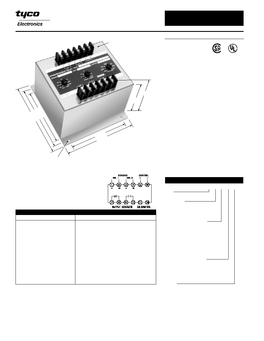
Notes:
1. Remove black cover screws to gain access to the adjustment potentiometers.
2. Clockwise rotation increases the trip differential setting.
3. Calibration terminals (11) (12) must be connected together to disable the phase angle
detector when setting the frequency difference trip point. Once it is set, the connection must
be removed.
13
/64" DIA.
4 MTG. HOLES
4
7/
16
5
1/
4
5
23
/
3
2
3 1/2
4 3/16
TERMINAL STRIPS
#6 - 32 SCREWS
4
1
/2
5
15 /32
25
WILMAR Protective Relays – WSYN Series
Note: Dimensions in inches. Multiply values by 25.4 for dimensions in mm.
相关PDF资料 |
PDF描述 |
|---|---|
| WTP4K36-15GMA | 4K X 36 MULTI DEVICE FIFO MODULE, 15 ns, CQMA132 |
| WTP4K36-15GM | 4K X 36 MULTI DEVICE FIFO MODULE, 15 ns, CQMA132 |
| WUF-12-3540 | POWER/SIGNAL RELAY, MOMENTARY, 5A (CONTACT), 28VDC (CONTACT), PANEL MOUNT |
| WUF-12-3540 | POWER/SIGNAL RELAY, SPST, MOMENTARY, PANEL MOUNT |
| WUF-23-5060 | POWER/SIGNAL RELAY, MOMENTARY, 5A (CONTACT), 28VDC (CONTACT), PANEL MOUNT |
相关代理商/技术参数 |
参数描述 |
|---|---|
| WSYN-50-120-12DC-A | 制造商:MACOM 制造商全称:Tyco Electronics 功能描述:Paralleling Relays |
| WSYS195N-PB-R | 制造商: 功能描述:Asus P4 3GHz Refurbished Computer without Operating System |
| WSYS199-NOHDD-PB | 制造商:Asus 功能描述:3.4GHz Barebone Computer W/o Hard Drive |
| WSZ672012209JBM000 | 制造商:Vishay Semiconductors 功能描述: |
| WSZ7532270R0JEK | 功能描述:线绕电阻器 - SMD 3.75watts 270ohms 5% RoHS:否 制造商:Ohmite 电阻:4.99 Ohms 容差:1 % 功率额定值:2 W 外壳代码 - in:4023 外壳代码 - mm:10357 温度系数:50 PPM / C 系列:RW2 工作温度范围:- 55 C to + 125 C 封装:Bulk |
发布紧急采购,3分钟左右您将得到回复。