- 您现在的位置:买卖IC网 > PDF目录40752 > X111-11 (POSITEK LTD) POSITION, LINEAR SENSOR-INDUCTIVE PDF资料下载
参数资料
| 型号: | X111-11 |
| 厂商: | POSITEK LTD |
| 元件分类: | Position, Linear, Inductive Sensor |
| 英文描述: | POSITION, LINEAR SENSOR-INDUCTIVE |
| 文件页数: | 4/4页 |
| 文件大小: | 243K |
| 代理商: | X111-11 |
INTRINSICALLY SAFE
BX002 and BX003 Sensor Barrier
3 & 5-WIRE CONNECTION INFORMATION
The following discussion about 3 and 5 wire connections between sensors and the Galvanic Isolation Amplifiers is
intended as an aid for end-users who are not familiar with the topic.
Whether opting for a pre-wired Positek Intrinsically Safe sensor or one with a connector, choosing the right mode of
connection and cable to suit the application requires consideration. Conductor resistance, a function of cross-section,
length and current, causes volts drop across cable. This can significantly alter the perceived accuracy of the sensor
which is ratiometric i.e. the output signal is directly affected by the supply voltage at the sensor.
3-wire connections are common for connecting sensors but accuracy can become an issue. Increasing conductor
cross-section reduces volts drop and is suitable for all but very long lengths or applications that require a high degree
of accuracy. Another factor to consider is conductor temperature. Fluctuations in temperature also cause minor
changes in resistance, the effects of which can be seen in the calculated examples below for 0.25mm2 and 2.5mm2
conductors at 20°C and 50°C.
Sensors supplied with cable are calibrated with the cable fitted which
negates errors due to conductor resistance at room temperature; however,
small errors due to temperature fluctuations should be expected.
Large cross-section cables are not always practical. For example, sensors
supplied with either the IP65 or IP67 connectors have a maximum
conductor size of 0.75mm2.
5-wire connections have significant benefits over three wire connections as
losses in the power and ground conductors are compensated. The Galvanic
Isolation Amplifier senses and dynamically adjusts the output voltage so
that the voltage at the sensor is correct, the effects of cable resistance and
associated temperature coefficients are eliminated. BX002 and BX003
amplifiers can compensate for up to 12 per conductor with a current flow
of 15mA, which is more than adequate for 150m of 0.25mm2 cable.
For this reason Positek recommends five wire connections for
cable lengths exceeding 10 metres.
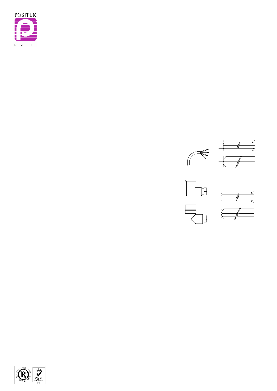
See illustrations right for examples of connecting a sensor to the Galvanic
Isolation Amplifier.
The following formulae can be used to calculate losses due to conductor cross-section and conductor temperature;
Resistance of the a single conductor is
R = ρ x L / A x (1 + TC x (T - Tamb)) where:
ρ
= resistivity of copper wire: 1.69x10⁻⁸m
L
= length of the wire: in metres
A
= area of the conductor cross section of the wire in metres2: e.g. 0.25mm2 conductor 0.25/10002 = 2.5x10⁻⁷m2
TC
= copper temperature coefficient: 3.9x10⁻³
T
= conductor temperature in °C
Tamb
= ambient temperature i.e. 20°C
Voltage at sensor
Vsensor = V - I x 2 x R where
V
= supply voltage from the amplifier
I
= the supply current: 10mA
R
= resistance of the a single conductor
Examples: (of 3-wire connections with the maximum 150 metres of cable, conductor sizes 0.252 and 2.5mm2 at 20°C and 50°C)
0.25mm2 cable at 20°C
R=1.69x10-8x150/2.5x10-7x(1+3.9x10-3x(20-20))
= 10.14
Vsensor=5–10x10-3x2x10.14
= 4.79V or 4.0% loss
0.25mm2 cable at 50°C
R=1.69x10-8x150/2.5x10-7x(1+3.9x10-3x(50-20))
= 11.33
Vsensor=5–10x10-3x2x11.33
= 4.77V or 4.5% loss
2.5mm2 cable at 20°C
R=1.69x10-8x150/2.5x10-6x(1+3.9x10-3x(20-20))
= 1.01
Vsensor=5–10x10-3x2x1.01
= 4.98V or 0.4% loss
2.5mm2 cable at 50°C
R=1.69x10-8x150/2.5x10-6x(1+3.9x10-3x(50-20))
= 1.13
Vsensor=5–10x10-3x2x1.13
= 4.97V or 0.45% loss
+V
O/P
0V
+V
O/P
0V
+Sense
I/P
-Sense
+V
+Sense
I/P
-Sense
0V
+V
0V
3-wire
Connections
5-wire
Sensor
Amplifier
0.75mm max.
3-wire
+V
O/P
0V
+V
O/P
0V
+Sense
I/P
-Sense
+V
+Sense
I/P
-Sense
0V
+V
0V
Connections
Terminals
5-wire
Sensor
Amplifier
For further information please contact:
www.positek.com sales@positek.com
Tel: +44(0)1242 820027 fax: +44(0)1242 820615
Positek Ltd, Andoversford Industrial Estate, Cheltenham GL54 4LB U.K.
相关PDF资料 |
PDF描述 |
|---|---|
| X32-20000-12 | QUARTZ CRYSTAL RESONATOR, 20 MHz |
| XCA4100AN | ABSOLUTE, PEIZORESISTIVE PRESSURE SENSOR, 100Psi, 2.25-4.25V, RECTANGULAR, THROUGH HOLE MOUNT |
| XCA460DN | DIFFERENTIAL, PEIZORESISTIVE PRESSURE SENSOR, 60Psi, 2.25-4.25V, RECTANGULAR, THROUGH HOLE MOUNT |
| XCA430AN | ABSOLUTE, PEIZORESISTIVE PRESSURE SENSOR, 30Psi, 2.25-4.25V, RECTANGULAR, THROUGH HOLE MOUNT |
| XCA405GN | GAGE, PEIZORESISTIVE PRESSURE SENSOR, 5Psi, 0.25-4.25V, RECTANGULAR, THROUGH HOLE MOUNT |
相关代理商/技术参数 |
参数描述 |
|---|---|
| X-11181-002 | 制造商:LINER 制造商全称:Linear Technology 功能描述:Offline Isolated Flyback LED Controller with Active PFC |
| X111820-PC1 | 制造商:Honeywell Sensing and Control 功能描述:20PC |
| X111R00 | 制造商:Laird Technologies Inc 功能描述: |
| X112-133.33M | 制造商:CONNOR-WINFIELD 制造商全称:Connor-Winfield Corporation 功能描述:5.0x7.0mm Surface Mount LVCMOS Clock Oscillator Series |
| X112196-PC | 制造商:Honeywell Sensing and Control 功能描述:20PC |
发布紧急采购,3分钟左右您将得到回复。