参数资料
| 型号: | X1205S8I |
| 厂商: | Intersil |
| 文件页数: | 10/22页 |
| 文件大小: | 0K |
| 描述: | IC RTC/CALENDAR 2-WIRE 8-SOIC |
| 标准包装: | 100 |
| 类型: | 时钟/日历 |
| 特点: | 警报器,闰年 |
| 时间格式: | HH:MM:SS(12/24 小时) |
| 数据格式: | YY-MM-DD-dd |
| 接口: | I²C,2 线串口 |
| 电源电压: | 2.7 V ~ 5.5 V |
| 电压 - 电源,电池: | 1.8 V ~ 5.5 V |
| 工作温度: | -40°C ~ 85°C |
| 安装类型: | 表面贴装 |
| 封装/外壳: | 8-SOIC(0.154",3.90mm 宽) |
| 供应商设备封装: | 8-SOIC |
| 包装: | 管件 |
18
FN8097.3
May 2, 2006
A final application for the ATR control is in-circuit cali-
bration for high accuracy applications, along with a
temperature sensor chip. Once the RTC circuit is pow-
ered up with battery backup, the PHZ output is set at
32.768kHz and frequency drift is measured. The ATR
control is then adjusted to a setting which minimizes
drift. Once adjusted at a particular temperature, it is
possible to adjust at other discrete temperatures for
minimal overall drift, and store the resulting settings in
the EEPROM. Extremely low overall temperature drift
is possible with this method. The Intersil evaluation
board contains the circuitry necessary to implement
this control.
For more detailed operation see Intersil’s application
note AN154 on Intersil’s website at www.intersil.com.
Layout Considerations
The crystal input at X1 has a very high impedance and
will pick up high frequency signals from other circuits on
the board. Since the X2 pin is tied to the other side of
the crystal, it is also a sensitive node. These signals can
couple into the oscillator circuit and produce double
clocking or mis-clocking, seriously affecting the accu-
racy of the RTC. Care needs to be taken in layout of the
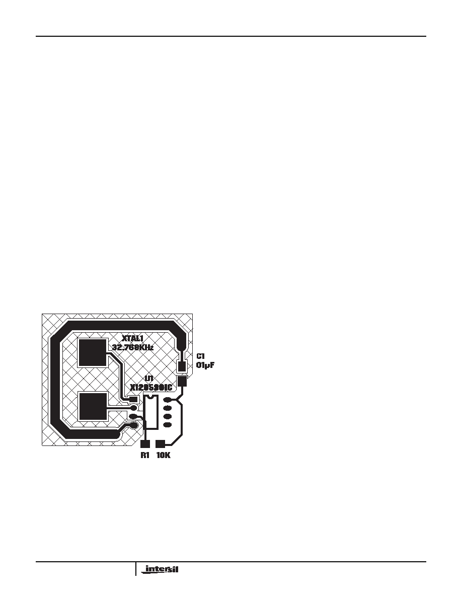
RTC circuit to avoid noise pickup. Below in Figure 12 is
a suggested layout for the X1205 SOIC device.
Figure 12. Suggested Layout for Intersil RTC in SO-8
The X1 and X2 connections to the crystal are to be
kept as short as possible. A thick ground trace around
the crystal is advised to minimize noise intrusion, but
ground near the X1 and X2 pins should be avoided as
it will add to the load capacitance at those pins. Keep
in mind these guidelines for other PCB layers in the
vicinity of the RTC device. A small decoupling capaci-
tor at the Vcc pin of the chip is mandatory, with a solid
connection to ground.
Assembly
Most electronic circuits do not have to deal with
assembly issues, but with the RTC devices assembly
includes insertion or soldering of a live battery into an
unpowered circuit. If a socket is soldered to the board,
and a battery is inserted in final assembly, then there
are no issues with operation of the RTC. If the battery
is soldered to the board directly, then the RTC device
Vback pin will see some transient upset from either
soldering tools or intermittent battery connections
which can stop the circuit from oscillating. Once the
battery is soldered to the board, the only way to assure
the circuit will start up is to momentarily (very short
period of time!) short the Vback pin to ground and the
circuit will begin to oscillate.
Oscillator Measurements
When a proper crystal is selected and the layout guide-
lines above are observed, the oscillator should start up
in most circuits in less than one second. Some circuits
may take slightly longer, but startup should definitely
occur in less than 5 seconds. When testing RTC cir-
cuits, the most common impulse is to apply a scope
probe to the circuit at the X2 pin (oscillator output) and
observe the waveform. DO NOT DO THIS! Although in
some cases you may see a useable waveform, due to
the parasitics (usually 10pF to ground) applied with the
scope probe, there will be no useful information in that
waveform other than the fact that the circuit is oscillat-
ing. The X2 output is sensitive to capacitive impedance
so the voltage levels and the frequency will be affected
by the parasitic elements in the scope probe. Applying a
scope probe can possibly cause a faulty oscillator to
start up, hiding other issues (although in the Intersil
RTC’s, the internal circuitry assures startup when using
the proper crystal and layout).
The best way to analyze the RTC circuit is to power it
up and read the real time clock as time advances, or if
the chip has the PHZ output, look at the output of that
pin on an oscilloscope (after enabling it with the con-
trol register, and using a pullup resistor for an open-
drain output). Alternatively, the X1226/1286/1205
devices have an IRQ- output which can be checked by
setting an alarm for each minute. Using the pulse
interrupt mode setting, the once-per-minute interrupt
functions as an indication of proper oscillation.
Backup Battery Operation
Many types of batteries can be used with the Intersil
RTC products. 3.0V or 3.6V Lithium batteries are
appropriate, and sizes are available that can power a
Intersil RTC device for up to 10 years. Another option
is to use a supercapacitor for applications where Vcc
may disappear intermittently for short periods of time.
X1205
相关PDF资料 |
PDF描述 |
|---|---|
| VI-26F-MX-B1 | CONVERTER MOD DC/DC 72V 75W |
| VE-B3K-IU-F4 | CONVERTER MOD DC/DC 40V 200W |
| MCP4231T-103E/ML | IC POT DGTL DUAL 10K SPI 16QFN |
| M83723/75R18087 | CONN PLUG 8POS STRAIGHT W/SCKT |
| X1205S8 | IC RTC/CALENDAR 2-WIRE 8-SOIC |
相关代理商/技术参数 |
参数描述 |
|---|---|
| X1205S8IT1 | 功能描述:IC RTC/CALENDAR 2-WIRE 8-SOIC RoHS:否 类别:集成电路 (IC) >> 时钟/计时 - 实时时钟 系列:- 产品培训模块:Obsolescence Mitigation Program 标准包装:1 系列:- 类型:时钟/日历 特点:警报器,闰年,SRAM 存储容量:- 时间格式:HH:MM:SS(12/24 小时) 数据格式:YY-MM-DD-dd 接口:SPI 电源电压:2 V ~ 5.5 V 电压 - 电源,电池:- 工作温度:-40°C ~ 85°C 安装类型:表面贴装 封装/外壳:8-WDFN 裸露焊盘 供应商设备封装:8-TDFN EP 包装:管件 |
| X1205S8IZ | 制造商:Intersil Corporation 功能描述:Real Time Clock IC |
| X1205S8IZT1 | 制造商:INTERSIL 制造商全称:Intersil Corporation 功能描述:2-Wire RTC Real Time Clock/Calendar |
| X1205S8T1 | 功能描述:IC RTC/CALENDAR 2-WIRE 8-SOIC RoHS:否 类别:集成电路 (IC) >> 时钟/计时 - 实时时钟 系列:- 产品培训模块:Obsolescence Mitigation Program 标准包装:1 系列:- 类型:时钟/日历 特点:警报器,闰年,SRAM 存储容量:- 时间格式:HH:MM:SS(12/24 小时) 数据格式:YY-MM-DD-dd 接口:SPI 电源电压:2 V ~ 5.5 V 电压 - 电源,电池:- 工作温度:-40°C ~ 85°C 安装类型:表面贴装 封装/外壳:8-WDFN 裸露焊盘 供应商设备封装:8-TDFN EP 包装:管件 |
| X1205S8Z | 功能描述:IC RTC/CALENDAR/ALARM 4K 8-SOIC RoHS:是 类别:集成电路 (IC) >> 时钟/计时 - 实时时钟 系列:- 产品培训模块:Obsolescence Mitigation Program 标准包装:1 系列:- 类型:时钟/日历 特点:警报器,闰年,SRAM 存储容量:- 时间格式:HH:MM:SS(12/24 小时) 数据格式:YY-MM-DD-dd 接口:SPI 电源电压:2 V ~ 5.5 V 电压 - 电源,电池:- 工作温度:-40°C ~ 85°C 安装类型:表面贴装 封装/外壳:8-WDFN 裸露焊盘 供应商设备封装:8-TDFN EP 包装:管件 |
发布紧急采购,3分钟左右您将得到回复。