- 您现在的位置:买卖IC网 > PDF目录205930 > X5643S14I 1-CHANNEL POWER SUPPLY MANAGEMENT CKT, PDSO14 PDF资料下载
参数资料
| 型号: | X5643S14I |
| 元件分类: | 电源管理 |
| 英文描述: | 1-CHANNEL POWER SUPPLY MANAGEMENT CKT, PDSO14 |
| 封装: | PLASTIC, SOIC-14 |
| 文件页数: | 1/19页 |
| 文件大小: | 116K |
| 代理商: | X5643S14I |
REV 1.1.1 3/5/01
Characteristics subject to change without notice.
1 of 19
www.xicor.com
Replaces X25643/X25645
CPU Supervisor with 64Kbit SPI EEPROM
X5643/X5645
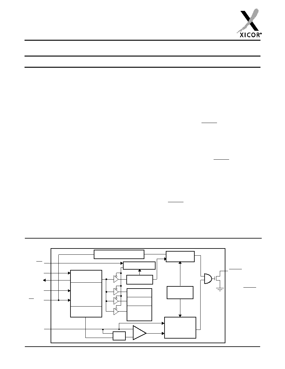
BLOCK DIAGRAM
Watchdog
Timer Reset
Data
Register
Command
Decode &
Control
Logic
SI
SO
SCK
CS/WDI
VCC
Reset &
Watchdog
Timebase
Power On and
Generation
VTRIP
+
-
RESET/RESET
Reset
Low Voltage
Status
Register
Protect Logic
16Kbits
32Kbits
EEPROM
Array
Watchdog Transition
Detector
WP
VCC Threshold
Reset logic
X5643 = RESET
X5645 = RESET
FEATURES
Selectable watchdog timer
Low VCC detection and reset assertion
—Five standard reset threshold voltages
—Re-program low VCC reset threshold voltage
using special programming sequence
—Reset signal valid to VCC = 1V
Determine watchdog or low voltage reset with a
volatile ag bit
Long battery life with low power consumption
—<50A max standby current, watchdog on
—<1A max standby current, watchdog off
—<400A max active current during read
64Kbits of EEPROM
Built-in inadvertent write protection
—Power-up/power-down protection circuitry
—Protect 0, 1/4, 1/2 or all of EEPROM array with
Block Lock protection
—In circuit programmable ROM mode
2MHz SPI interface modes (0,0 & 1,1)
Minimize EEPROM programming time
—32-byte page write mode
—Self-timed write cycle
—5ms write cycle time (typical)
2.7V to 5.5V and 4.5V to 5.5V power supply
operation
Available packages
—8-lead PDIP, 14-lead SOIC
DESCRIPTION
These devices combine four popular functions, Power-
on Reset Control, Watchdog Timer, Supply Voltage
Supervision, and Block Lock Protect Serial EEPROM
Memory in one package. This combination lowers sys-
tem cost, reduces board space requirements, and
increases reliability.
Applying power to the device activates the power on
reset circuit which holds RESET/RESET active for a
period of time. This allows the power supply and oscilla-
tor to stabilize before the processor can execute code.
The Watchdog Timer provides an independent protection
mechanism for microcontrollers. When the microcon-
troller fails to restart a timer within a selectable time out
interval, the device activates the RESET/RESET signal.
The user selects the interval from three preset values.
Once selected, the interval does not change, even after
cycling the power.
The device’s low VCC detection circuitry protects the
user’s system from low voltage conditions, resetting
the system when VCC falls below the minimum VCC
trip point. RESET/RESET is asserted until VCC returns
to proper operating level and stabilizes. Five industry
standard VTRIP thresholds are available, however,
Xicor’s unique circuits allow the threshold to be repro-
grammed to meet custom requirements or to ne-tune
the threshold for applications requiring higher precision.
相关PDF资料 |
PDF描述 |
|---|---|
| XA1N300M | POWER/SIGNAL RELAY, DPDT, MOMENTARY, 0.036A (COIL), 28VDC (COIL), 1008mW (COIL), 5A (CONTACT), 28VDC (CONTACT), SOCKET MOUNT |
| XJ7N300M | POWER/SIGNAL RELAY, DPDT, MOMENTARY, 0.036A (COIL), 28VDC (COIL), 1008mW (COIL), 5A (CONTACT), 28VDC (CONTACT), THROUGH HOLE-RIGHT ANGLE MOUNT |
| XA3S100E-4FGG400I | FPGA, 240 CLBS, 100000 GATES, 572 MHz, PBGA400 |
| XA9536XL-10VQG44I | FLASH PLD, PQFP44 |
| XA9536XL-10VQG44Q | FLASH PLD, PQFP44 |
相关代理商/技术参数 |
参数描述 |
|---|---|
| X5643S14I-2.7 | 功能描述:IC CPU SUPRV 64K EE RST LO SO14 RoHS:否 类别:集成电路 (IC) >> PMIC - 监控器 系列:- 标准包装:1 系列:- 类型:简单复位/加电复位 监视电压数目:1 输出:开路漏极或开路集电极 复位:低有效 复位超时:标准传输延迟为 60 µs 电压 - 阀值:3V 工作温度:-40°C ~ 85°C 安装类型:表面贴装 封装/外壳:SC-74A,SOT-753 供应商设备封装:SOT-23-5 包装:Digi-Reel® 其它名称:LM8364BALMF30DKR |
| X5643S14I-4.5A | 制造商:XICOR 制造商全称:Xicor Inc. 功能描述:CPU Supervisor with 64Kbit SPI EEPROM |
| X5643S8-1.8 | 制造商:未知厂家 制造商全称:未知厂家 功能描述:SPI Serial EEPROM with Supervisory Features |
| X5643S8-2.7 | 制造商:未知厂家 制造商全称:未知厂家 功能描述:SPI Serial EEPROM with Supervisory Features |
| X5643S8-2.7A | 制造商:未知厂家 制造商全称:未知厂家 功能描述:SPI Serial EEPROM with Supervisory Features |
发布紧急采购,3分钟左右您将得到回复。