参数资料
| 型号: | X90100M8IT1 |
| 厂商: | Intersil |
| 文件页数: | 3/7页 |
| 文件大小: | 0K |
| 描述: | IC DIGITAL CAPACITOR NV 8-MSOP |
| 标准包装: | 2,500 |
| 类型: | 数字电容器 |
| 应用: | 无线 |
| 安装类型: | 表面贴装 |
| 封装/外壳: | 8-TSSOP,8-MSOP(0.118",3.00mm 宽) |
| 供应商设备封装: | 8-MSOP |
| 包装: | 带卷 (TR) |
3
FN8156.0
February 2, 2005
Absolute Maximum Ratings
Temperature under bias . . . . . . . . . . . . . . . . . . . . . .-65
°C to +135°C
Storage temperature . . . . . . . . . . . . . . . . . . . . . . . .-65°C to +150°C
Voltage on CS, INC, U/D, CP, and
CM with respect to VSS . . . . . . . . . . . . . . . . . . . . . . . . -1V to +7V
V = |VCP-VCM|. . . . . . . . . . . . . . . . . . . . . . . . . . . . . . . . . . . . . . .5V
Lead temperature (soldering 10 seconds) . . . . . . . . . . . . . . . . 300°C
CAUTION: Stresses above those listed under “Absolute Maximum Ratings” may cause permanent damage to the device. This is a stress rating only; the functional
operation of the device (at these or any other conditions above those listed in the operational sections of this specification) is not implied. Exposure to absolute
maximum rating conditions for extended periods may affect device reliability.
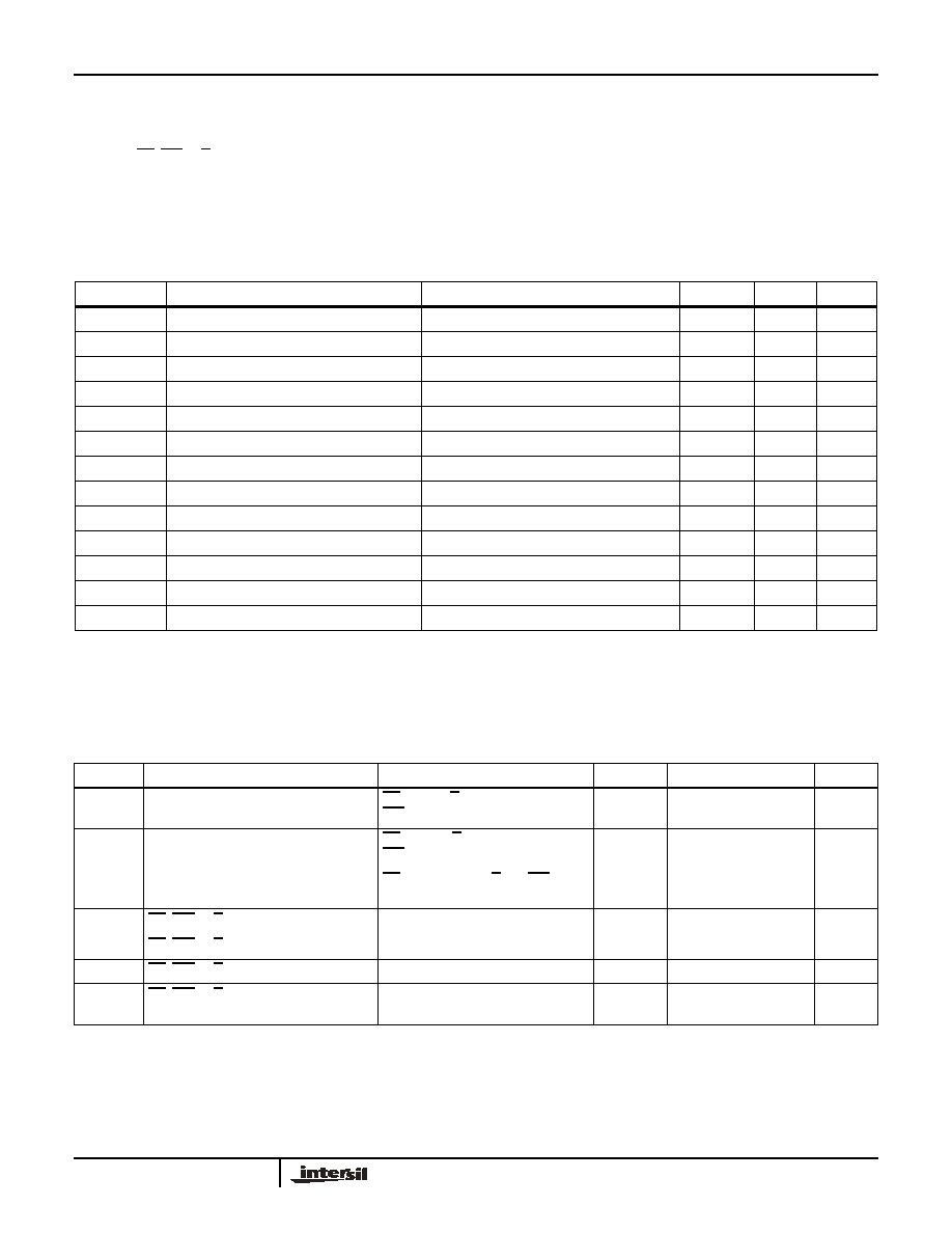
Capacitor Specifications
VCC = +5V, TA = 25°C, single ended mode, CM = 0V, unless otherwise stated.
SYMBOL
PARAMETER
TEST CONDITIONS/NOTES
MIN
TYP (4)
MAX
UNIT
Absolute accuracy
±15
%
VCp
Cp terminal voltage
0
VCC
V
VCm
Cm terminal voltage
0
VCC
V
C
Capacitance increments
0.23
pF
C
Capacitance range
7pF
CTOTAL
Capacitance at Code=0
7.5
pF
CTOTAL
Capacitance at Code=31
14.5
pF
Q
Quality factor(5)
f = 315MHz
7
Resolution
5bits
INL
Absolute linearity error(1)
±0.15
lsb
DNL
Relative linearity error(2)
±0.15
lsb
TC1
CTOTAL Temperature Coefficient(5)
Differential Mode
±50
ppm/°C
VCC
Supply Voltage
2.7
5.5
V
Notes: (1) Absolute linearity is used to determine actual capacitance versus expected capacitance = C(n)(actual) - C(n) (expected) = ±0.15 Ml.
(2) Relative linearity is a measure of the error in step size between settings = C(n+1)-[C(n) + Ml] = ±0.15 Ml.
(3) lsb = least significant bit = CTOT/31.
(4) Typical values are for TA = 25°C and nominal supply voltage.
(5) This parameter is not 100% tested.
DC Electrical Specifications
VCC = 5V, TA = 25°C unless otherwise specified.
SYMBOL
PARAMETER
TEST CONDITIONS
MIN
TYP (4)
MAX
UNIT
ICC1
VCC active current (Increment)
CS = VIL, U/D = VIL or VIH and
INC = 0.4V @ max. tCYC
50
100
A
ICC2
VCC active current (Store) (EEPROM
Store)
CS = VIH, U/D = VIL or VIH and
INC =VIH @ max. tWR
250
500
A
ISB
Standby supply current
CS = VCC - 0.3V, U/D and INC = VSS
or VCC - 0.3V
0.5
2
A
ILI
CS, INC, U/D input leakage current
VIN = VSS
-15
A
VIH
CS, INC, U/D input HIGH voltage
VCC x 0.7
VCC + 0.5
V
VIL
CS, INC, U/D input LOW voltage
-0.5
VCC x 0.1
V
CIN(5)
CS, INC, U/D input capacitance
VCC = 5V, VIN = VSS, TA = 25°C,
f=1MHz
10
pF
X90100
相关PDF资料 |
PDF描述 |
|---|---|
| X90100M8I | IC DIGITAL CAPACITOR NV 8-MSOP |
| AMC40DRTF-S13 | CONN EDGECARD 80POS .100 EXTEND |
| AMM18DTBT | CONN EDGECARD 36POS R/A .156 SLD |
| TLE8261-2E | IC SYSTEM BASIS CHIP DSO-36 |
| AMM18DTAT | CONN EDGECARD 36POS R/A .156 SLD |
相关代理商/技术参数 |
参数描述 |
|---|---|
| X90100M8IZ | 功能描述:射频无线杂项 32-TAP 7 5PF TO 14PF DIGTL CAPACITOR INT RoHS:否 制造商:Texas Instruments 工作频率:112 kHz to 205 kHz 电源电压-最大:3.6 V 电源电压-最小:3 V 电源电流:8 mA 最大功率耗散: 工作温度范围:- 40 C to + 110 C 封装 / 箱体:VQFN-48 封装:Reel |
| X90100M8IZT1 | 功能描述:射频无线杂项 32-TAP 7 5PF TO 14PF DIGTL CAPACITOR INT RoHS:否 制造商:Texas Instruments 工作频率:112 kHz to 205 kHz 电源电压-最大:3.6 V 电源电压-最小:3 V 电源电流:8 mA 最大功率耗散: 工作温度范围:- 40 C to + 110 C 封装 / 箱体:VQFN-48 封装:Reel |
| X90100MI | 制造商:XICOR 制造商全称:Xicor Inc. 功能描述:NV Electronically Programmable Capacitor |
| X90100P8I | 制造商:Intersil Corporation 功能描述:X90100P8I - Rail/Tube |
| X90100X8I | 制造商:XICOR 制造商全称:Xicor Inc. 功能描述:NV Electronically Programmable Capacitor |
发布紧急采购,3分钟左右您将得到回复。