参数资料
| 型号: | X9251TS24IZ-2.7T1 |
| 厂商: | Intersil |
| 文件页数: | 18/20页 |
| 文件大小: | 0K |
| 描述: | IC XDCP QUAD 256TAP 100K 24-SOIC |
| 产品培训模块: | Solutions for Industrial Control Applications |
| 标准包装: | 1,000 |
| 系列: | XDCP™ |
| 接片: | 256 |
| 电阻(欧姆): | 100k |
| 电路数: | 4 |
| 温度系数: | 标准值 ±300 ppm/°C |
| 存储器类型: | 非易失 |
| 接口: | 6 线 SPI(芯片选择,设备位址) |
| 电源电压: | 2.7 V ~ 5.5 V |
| 工作温度: | -40°C ~ 85°C |
| 安装类型: | 表面贴装 |
| 封装/外壳: | 24-SOIC(0.295",7.50mm 宽) |
| 供应商设备封装: | 24-SOIC |
| 包装: | 带卷 (TR) |
7
FN8166.5
April 13, 2007
Instructions
Four of the nine instructions are three bytes in length. These
instructions are:
Read Wiper Counter Register – read the current wiper
position of the selected potentiometer,
Write Wiper Counter Register – change current wiper
position of the selected potentiometer,
Read Data Register – read the contents of the selected
Data Register,
Write Data Register – write a new value to the selected
Data Register,
Read Status – this command returns the contents of the
WIP bit which indicates if the internal write cycle is in
progress.
The basic sequence of the three byte instructions is
illustrated in Figure 3. These three-byte instructions
exchange data between the WCR and one of the Data
Registers. A transfer from a Data Register to a WCR is
essentially a write to a static RAM, with the static RAM
controlling the wiper position. The response of the wiper to
this action is delayed by tWRL. A transfer from the WCR
(current wiper position), to a Data Register is a write to non-
volatile memory and takes a minimum of tWR to complete.
The transfer can occur between one of the four
potentiometer’s WCR, and one of its associated registers,
DRs; or it may occur globally, where the transfer occurs
between all potentiometers and one associated register. The
Read Status Register instruction is the only unique format
(See Figure 5).
Four instructions require a two-byte sequence to complete.
These instructions transfer data between the host and the
X9251; either between the host and one of the data registers
or directly between the host and the Wiper Counter Register.
These instructions are:
XFR Data Register to Wiper Counter Register – This
transfers the contents of one specified Data Register to
the associated Wiper Counter Register.
XFR Wiper Counter Register to Data Register – This
transfers the contents of the specified Wiper Counter
Register to the specified associated Data Register.
Global XFR Data Register to Wiper Counter
Register – This transfers the contents of all specified Data
Registers to the associated Wiper Counter Registers.
Global XFR Wiper Counter Register to Data
Register – This transfers the contents of all Wiper
Counter Registers to the specified associated Data
Registers.
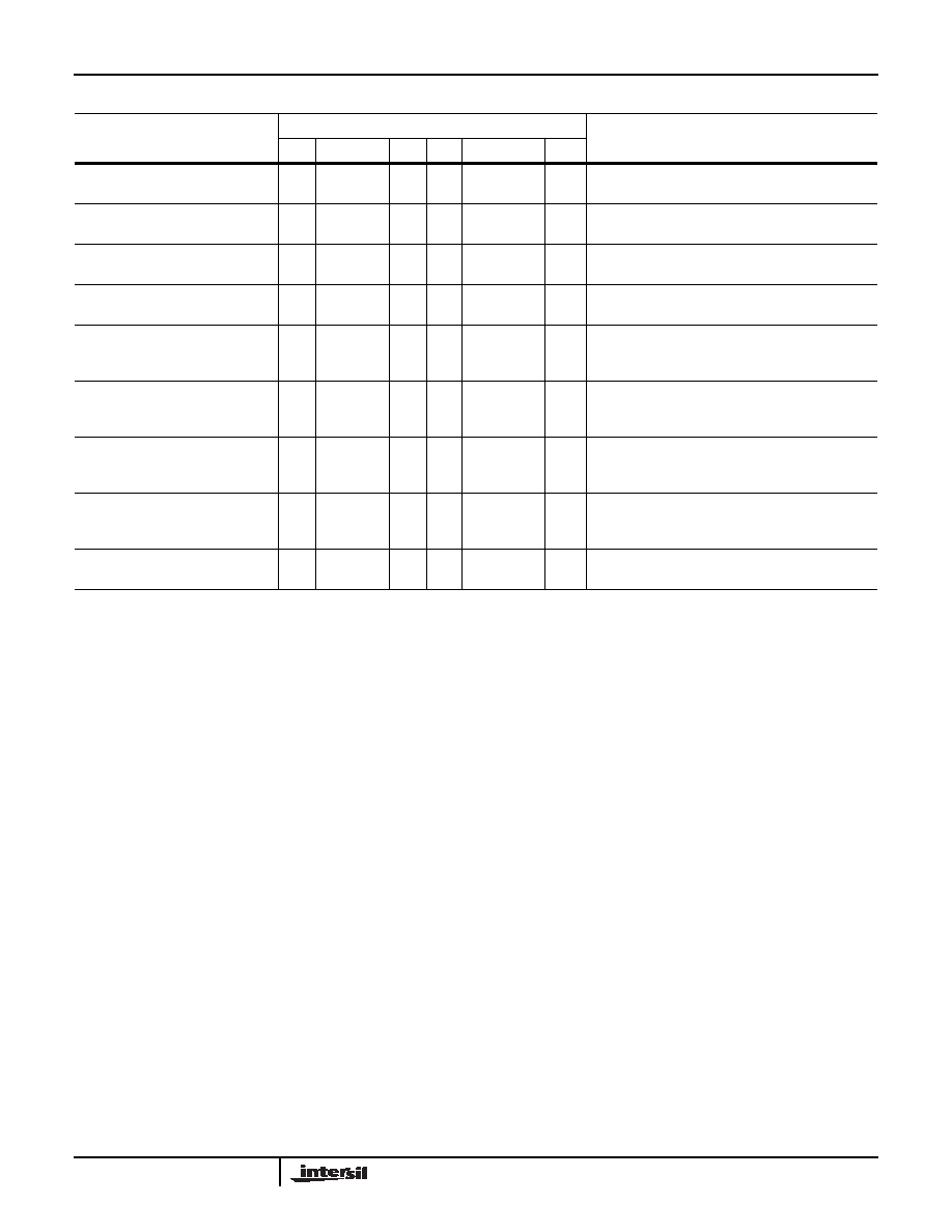
TABLE 5. INSTRUCTION SET
INSTRUCTION
INSTRUCTION SET
OPERATION
I3
I2
I1
I0
RB
RA
P1
P0
Read Wiper Counter Register
1
0
1
0
1/0
Read the contents of the Wiper Counter Register
pointed to by P1 - P0
Write Wiper Counter Register
1
0
1
0
1/0
Write new value to the Wiper Counter
Register pointed to by P1 - P0
Read Data Register
1
0
1
1/0
Read the contents of the Data Register pointed to
by P1 - P0 and RB - RA
Write Data Register
1
0
1/0
Write new value to the Data Register
pointed to by P1 - P0 and RB - RA
XFR Data Register to
Wiper Counter Register
1
0
1
1/0
Transfer the contents of the Data Register pointed to
by P1 - P0 and RB - RA to its
associated Wiper Counter Register
XFR Wiper Counter
Register to Data Register
1
0
1/0
Transfer the contents of the Wiper Counter Register
pointed to by P1 - P0 to the Data Register pointed
to by RB - RA
Global XFR Data Registers to
Wiper Counter Registers
0
1
1/0
0
Transfer the contents of the Data Registers pointed
to by RB - RA of all four pots to their respective
Wiper Counter Registers
Global XFR Wiper Counter
Registers to Data Register
1
0
1/0
0
Transfer the contents of both Wiper Counter
Registers to their respective data Registers pointed
to by RB - RA of all four pots
Increment/Decrement
Wiper Counter Register
0
1
0
1/0
Enable Increment/decrement of the Control Latch
pointed to by P1 - P0
NOTE: 1/0 = data is one or zero
X9251
相关PDF资料 |
PDF描述 |
|---|---|
| VE-BWX-MY-F3 | CONVERTER MOD DC/DC 5.2V 50W |
| VI-25Y-MU | CONVERTER MOD DC/DC 3.3V 132W |
| VI-20H-MX-B1 | CONVERTER MOD DC/DC 52V 75W |
| VE-BWX-MY-F1 | CONVERTER MOD DC/DC 5.2V 50W |
| X9251US24IZ-2.7T1 | IC POT DGTL QUAD 50K OHM 24-SOIC |
相关代理商/技术参数 |
参数描述 |
|---|---|
| X9251TS24IZT1 | 功能描述:IC XDCP QUAD 256TAP 100K 24-SOIC RoHS:是 类别:集成电路 (IC) >> 数据采集 - 数字电位器 系列:XDCP™ 产品培训模块:Lead (SnPb) Finish for COTS Obsolescence Mitigation Program 标准包装:2,500 系列:- 接片:256 电阻(欧姆):100k 电路数:2 温度系数:标准值 35 ppm/°C 存储器类型:易失 接口:6 线串行(芯片选择,递增,增/减) 电源电压:2.6 V ~ 5.5 V 工作温度:-40°C ~ 125°C 安装类型:表面贴装 封装/外壳:14-TSSOP(0.173",4.40mm 宽) 供应商设备封装:14-TSSOP 包装:带卷 (TR) |
| X9251TS24T1 | 功能描述:IC XDCP QUAD 256TAP 100K 24-SOIC RoHS:否 类别:集成电路 (IC) >> 数据采集 - 数字电位器 系列:XDCP™ 标准包装:2,500 系列:XDCP™ 接片:256 电阻(欧姆):100k 电路数:1 温度系数:标准值 ±300 ppm/°C 存储器类型:非易失 接口:I²C(设备位址) 电源电压:2.7 V ~ 5.5 V 工作温度:0°C ~ 70°C 安装类型:表面贴装 封装/外壳:14-TSSOP(0.173",4.40mm 宽) 供应商设备封装:14-TSSOP 包装:带卷 (TR) |
| X9251TS24Z | 功能描述:IC XDCP QUAD 256TAP 100K 24-SOIC RoHS:是 类别:集成电路 (IC) >> 数据采集 - 数字电位器 系列:XDCP™ 产品培训模块:Lead (SnPb) Finish for COTS Obsolescence Mitigation Program 标准包装:2,500 系列:- 接片:256 电阻(欧姆):100k 电路数:2 温度系数:标准值 35 ppm/°C 存储器类型:易失 接口:6 线串行(芯片选择,递增,增/减) 电源电压:2.6 V ~ 5.5 V 工作温度:-40°C ~ 125°C 安装类型:表面贴装 封装/外壳:14-TSSOP(0.173",4.40mm 宽) 供应商设备封装:14-TSSOP 包装:带卷 (TR) |
| X9251TS24Z-2.7 | 功能描述:IC XDCP QUAD 256TAP 100K 24-SOIC RoHS:是 类别:集成电路 (IC) >> 数据采集 - 数字电位器 系列:XDCP™ 产品培训模块:Lead (SnPb) Finish for COTS Obsolescence Mitigation Program 标准包装:2,500 系列:- 接片:256 电阻(欧姆):100k 电路数:2 温度系数:标准值 35 ppm/°C 存储器类型:易失 接口:6 线串行(芯片选择,递增,增/减) 电源电压:2.6 V ~ 5.5 V 工作温度:-40°C ~ 125°C 安装类型:表面贴装 封装/外壳:14-TSSOP(0.173",4.40mm 宽) 供应商设备封装:14-TSSOP 包装:带卷 (TR) |
| X9251TS24Z-2.7T1 | 功能描述:IC XDCP QUAD 256TAP 100K 24-SOIC RoHS:是 类别:集成电路 (IC) >> 数据采集 - 数字电位器 系列:XDCP™ 产品培训模块:Lead (SnPb) Finish for COTS Obsolescence Mitigation Program 标准包装:2,500 系列:- 接片:256 电阻(欧姆):100k 电路数:2 温度系数:标准值 35 ppm/°C 存储器类型:易失 接口:6 线串行(芯片选择,递增,增/减) 电源电压:2.6 V ~ 5.5 V 工作温度:-40°C ~ 125°C 安装类型:表面贴装 封装/外壳:14-TSSOP(0.173",4.40mm 宽) 供应商设备封装:14-TSSOP 包装:带卷 (TR) |
发布紧急采购,3分钟左右您将得到回复。