- 您现在的位置:买卖IC网 > PDF目录300143 > X9271UV-2.7 50K DIGITAL POTENTIOMETER, 3-WIRE SERIAL CONTROL INTERFACE, 256 POSITIONS, PDSO14 PDF资料下载
参数资料
| 型号: | X9271UV-2.7 |
| 元件分类: | 数字电位计 |
| 英文描述: | 50K DIGITAL POTENTIOMETER, 3-WIRE SERIAL CONTROL INTERFACE, 256 POSITIONS, PDSO14 |
| 封装: | PLASTIC, TSSOP-14 |
| 文件页数: | 5/23页 |
| 文件大小: | 151K |
| 代理商: | X9271UV-2.7 |
X9271
Characteristics subject to change without notice.
13 of 23
REV 1.2 4/13/04
www.xicor.com
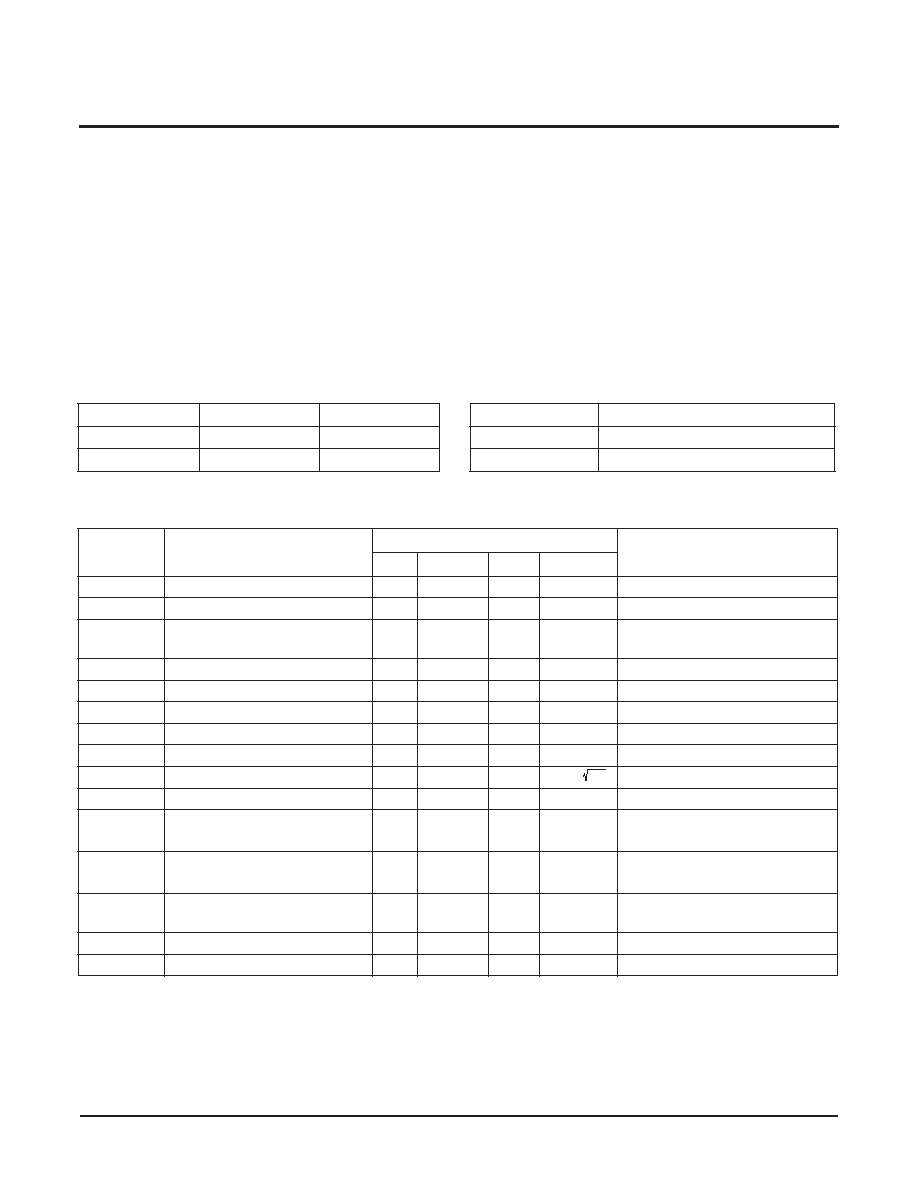
ABSOLUTE MAXIMUM RATINGS
Temperature under bias ................... –65
°C to +135°C
Storage temperature ........................ –65
°C to +150°C
Voltage on SCK any address input
with respect to VSS..................................–1V to +7V
V = |(VH–VL)|...................................................... 5.5V
Lead temperature (soldering, 10 seconds)........ 300
°C
IW (10 seconds).................................................. ±6mA
COMMENT
Stresses above those listed under “Absolute Maximum
Ratings” may cause permanent damage to the device.
This is a stress rating only; the functional operation of
the device (at these or any other conditions above
those listed in the operational sections of this
specication) is not implied. Exposure to absolute
maximum rating conditions for extended periods may
affect device reliability.
RECOMMENDED OPERATING CONDITIONS
Temp
Min.
Max.
Commercial
0
°C
+70
°C
Industrial
–40
°C
+85
°C
Device
Supply Voltage (VCC)
(4) Limits
X9271
5V
±10%
X9271-2.7
2.7V to 5.5V
ANALOG CHARACTERISTICS (Over recommended industrial operating conditions unless otherwise stated.)
Notes: (1) Absolute linearity is utilized to determine actual wiper voltage versus expected voltage as determined by wiper position when used
as a potentiometer.
(2) Relative linearity is utilized to determine the actual change in voltage between two successive tap positions when used as a
potentiometer. It is a measure of the error in step size.
(3) MI = RTOT / 255 or (RH – RL) / 255, single pot
(4) During power up VCC > VH, VL, and VW.
(5) n = 0, 1, 2, …,255; m =0, 1, 2, …., 254.
Symbol
Parameter
Limits
Test Conditions
Min.
Typ.
Max.
Units
RTOTAL
End to End Resistance
100
k
T version
RTOTAL
End to End Resistance
50
k
U version
End to End Resistance
Tolerance
±20
%
Power Rating
50
mW
25
°C, each pot
IW
Wiper Current
±3
mA
RW
Wiper Resistance
300
IW = ± 3mA @ VCC = 3V
RW
Wiper Resistance
150
IW = ± 3mA @ VCC = 5V
VTERM
Voltage on any RH or RL Pin
VSS
VCC
VVSS = 0V
Noise
-120
dBV
/ Hz
Ref: 1V
Resolution
0.4
%
Absolute Linearity(1)
±1
MI(3)
Rw(n)(actual) – Rw(n)(expected)
(5)
Relative Linearity(2)
±0.2
MI(3)
Rw(n + 1) – [Rw(n) + MI]
(5)
Temperature Coefficient of
RTOTAL
±300
ppm/
°C
Ratiometric Temp. Coefficient
20
ppm/°C
CH/CL/CW
Potentiometer Capacitancies
10/10/25
pF
See Macro model
相关PDF资料 |
PDF描述 |
|---|---|
| X9311TSI | 100K DIGITAL POTENTIOMETER, INCREMENT/DECREMENT CONTROL INTERFACE, 100 POSITIONS, PDSO8 |
| X9313ZMIT4 | 1K DIGITAL POTENTIOMETER, INCREMENT/DECREMENT CONTROL INTERFACE, 32 POSITIONS, PDSO8 |
| X9313UMI | 50K DIGITAL POTENTIOMETER, INCREMENT/DECREMENT CONTROL INTERFACE, 32 POSITIONS, PDSO8 |
| X9315LM-2.7 | 1000K DIGITAL POTENTIOMETER, INCREMENT/DECREMENT CONTROL INTERFACE, 32 POSITIONS, PDSO8 |
| X9315WMI-2.7T4 | 10K DIGITAL POTENTIOMETER, INCREMENT/DECREMENT CONTROL INTERFACE, 32 POSITIONS, PDSO8 |
相关代理商/技术参数 |
参数描述 |
|---|---|
| X9271UVI | 制造商:XICOR 制造商全称:Xicor Inc. 功能描述:Single Digitally-Controlled (XDCP) Potentiometer |
| X9271UVI-2.7 | 制造商:INTERSIL 制造商全称:Intersil Corporation 功能描述:Single Supply/Low Power/256-Tap/SPI Bus |
| X9271UXXX | 制造商:未知厂家 制造商全称:未知厂家 功能描述:DIGITAL POTENTIOMETER|CMOS|BGA|PLASTIC |
| X9271UXXX-2.7 | 制造商:未知厂家 制造商全称:未知厂家 功能描述:DIGITAL POTENTIOMETER|CMOS|BGA|PLASTIC |
| X9271UXXXI | 制造商:未知厂家 制造商全称:未知厂家 功能描述:DIGITAL POTENTIOMETER|CMOS|BGA|PLASTIC |
发布紧急采购,3分钟左右您将得到回复。