参数资料
| 型号: | X9315WSI-2.7 |
| 厂商: | Intersil |
| 文件页数: | 11/16页 |
| 文件大小: | 0K |
| 描述: | IC DIGITAL POT 10K 32TP 8SOIC |
| 标准包装: | 100 |
| 系列: | XDCP™ |
| 接片: | 32 |
| 电阻(欧姆): | 10k |
| 电路数: | 1 |
| 温度系数: | 标准值 ±300 ppm/°C |
| 存储器类型: | 非易失 |
| 接口: | 3 线串行(芯片选择,递增,增/减) |
| 电源电压: | 2.7 V ~ 5.5 V |
| 工作温度: | -40°C ~ 85°C |
| 安装类型: | 表面贴装 |
| 封装/外壳: | 8-SOIC(0.154",3.90mm 宽) |
| 供应商设备封装: | 8-SOIC |
| 包装: | 管件 |
| 产品目录页面: | 1238 (CN2011-ZH PDF) |
4
FN8179.2
December 21, 2009
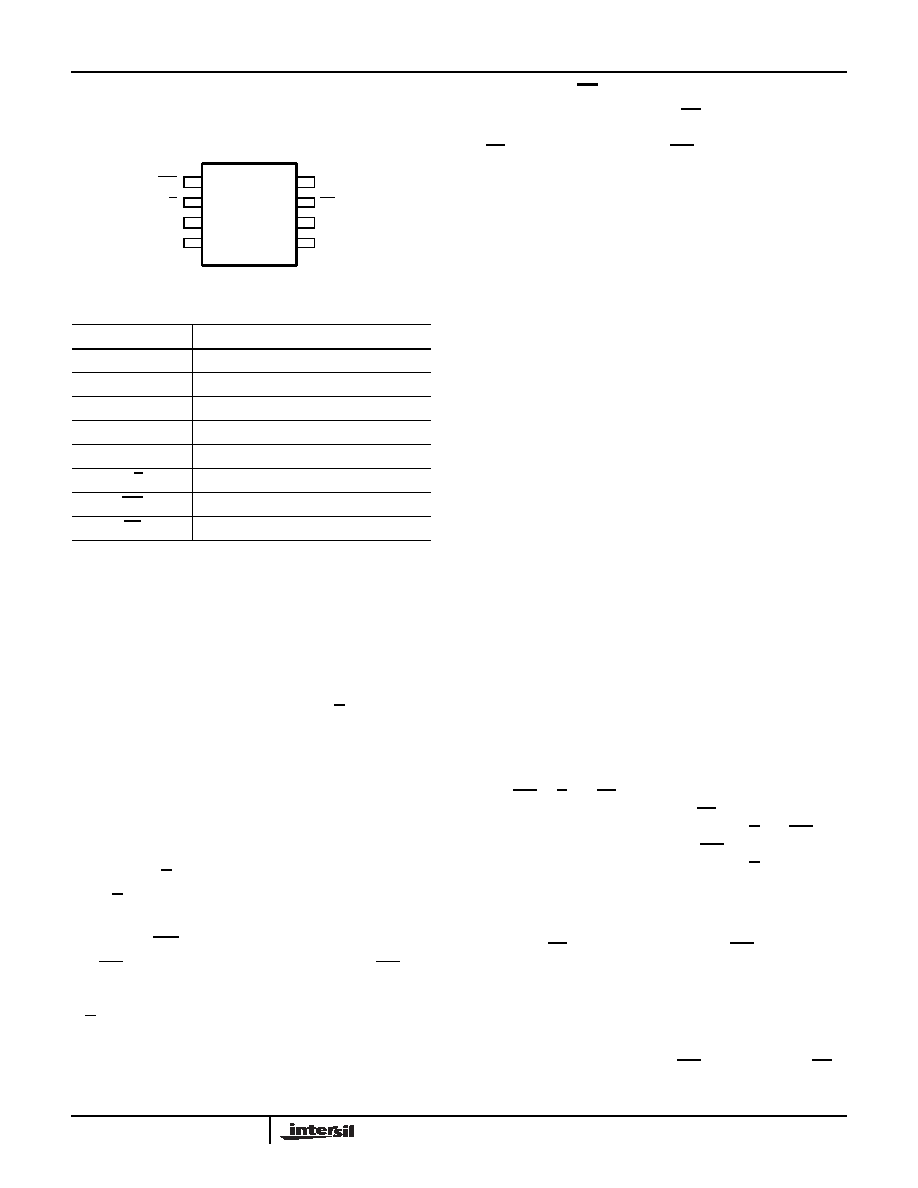
Pin Configuration
X9315
(8 LD MSOP, SOIC, PDIP)
TOP VIEW
Pin Description
RH/VH and RL/VL
The high (RH/VH) and low (RL/VL) terminals of the X9315
are equivalent to the fixed terminals of a mechanical
potentiometer. The minimum voltage is VSS and the
maximum is VCC. The terminology of RL/VL and RH/VH
references the relative position of the terminal in relation to
wiper movement direction selected by the U/D input, and not
the voltage potential on the terminal.
R
W
/V
W
RW/Vw is the wiper terminal and is equivalent to the movable
terminal of a mechanical potentiometer. The position of the
wiper within the array is determined by the control inputs.
The wiper terminal series resistance is typically 200
Ω at
VCC = 5V.
Up/Down (U/D)
The U/D input controls the direction of the wiper movement
and whether the counter is incremented or decremented.
Increment (INC)
The INC input is negative-edge triggered. Toggling INC will
move the wiper and either increment or decrement the
counter in the direction indicated by the logic level on the
U/D input.
Chip Select (CS)
The device is selected when the CS input is LOW. The
current counter value is stored in nonvolatile memory when
CS is returned HIGH while the INC input is also HIGH. After
the store operation is complete the X9315 will be placed in
the low power standby mode until the device is selected
once again.
Principles of Operation
There are three sections of the X9315: the input control,
counter and decode section; the nonvolatile memory; and
the resistor array. The input control section operates just like
an up/down counter. The output of this counter is decoded to
turn on a single electronic switch connecting a point on the
resistor array to the wiper output. Under the proper
conditions the contents of the counter can be stored in
nonvolatile memory and retained for future use. The resistor
array is comprised of 31 individual resistors connected in
series. At either end of the array and between each resistor
is an electronic switch that transfers the connection at that
point to the wiper.
The wiper, when at either fixed terminal, acts like its
mechanical equivalent and does not move beyond the last
position. That is, the counter does not wrap around when
clocked to either extreme.
The electronic switches on the device operate in a “make
before break” mode when the wiper changes tap positions. If
the wiper is moved several positions, multiple taps are
connected to the wiper for tIW (INC to VW change). The
RTOTAL value for the device can temporarily be reduced by
a significant amount if the wiper is moved several positions.
When the device is powered-down, the last wiper position
stored will be maintained in the nonvolatile memory. When
power is restored, the contents of the memory are recalled
and the wiper is set to the value last stored.
Instructions and Programming
The INC, U/D and CS inputs control the movement of the
wiper along the resistor array. With CS set LOW the device
is selected and enabled to respond to the U/D and INC
inputs. HIGH to LOW transitions on INC will increment or
decrement (depending on the state of the U/D input) a five
bit counter. The output of this counter is decoded to select
one of thirty two wiper positions along the resistive array.
The value of the counter is stored in nonvolatile memory
whenever CS transitions HIGH while the INC input is also
HIGH.
The system may select the X9315, move the wiper and
deselect the device without having to store the latest wiper
position in nonvolatile memory. After the wiper movement is
performed as described above and once the new position is
reached, the system must keep INC LOW while taking CS
HIGH. The new wiper position will be maintained until
Pin Names
SYMBOL
DESCRIPTION
RH/VH
High terminal
RW/VW
Wiper terminal
RL/VL
Low terminal
VSS
Ground
VCC
Supply voltage
U/D
Up/Down control input
INC
Increment control input
CS
Chip Select control input
VCC
CS
INC
U/D
RH/VH
VSS
1
2
3
4
8
7
6
5
X9315
RL/VL
RW/VW
X9315
相关PDF资料 |
PDF描述 |
|---|---|
| DS1388Z-33+T&R | IC RTC I2C W/CHARGER 8-SOIC |
| ISL22313UFU10Z | IC POT DGTL 256TP LN LP 10-MSOP |
| DS1307 | IC RTC SERIAL 512K 8-DIP |
| VE-B62-MV | CONVERTER MOD DC/DC 15V 150W |
| ISL22416WFU10Z | IC POT DGTL 128TP LN LP 10-MSOP |
相关代理商/技术参数 |
参数描述 |
|---|---|
| X9315WSIT1 | 功能描述:IC XDCP 32-TAP 10K 3WIRE 8-SOIC RoHS:否 类别:集成电路 (IC) >> 数据采集 - 数字电位器 系列:XDCP™ 产品培训模块:Lead (SnPb) Finish for COTS Obsolescence Mitigation Program 标准包装:2,500 系列:- 接片:32 电阻(欧姆):50k 电路数:1 温度系数:标准值 50 ppm/°C 存储器类型:易失 接口:3 线串行(芯片选择,递增,增/减) 电源电压:2.7 V ~ 5.5 V 工作温度:-40°C ~ 85°C 安装类型:表面贴装 封装/外壳:SOT-23-6 细型,TSOT-23-6 供应商设备封装:TSOT-23-6 包装:带卷 (TR) |
| X9315WSIT2 | 功能描述:IC XDCP 32-TAP 10K 3WIRE 8-SOIC RoHS:否 类别:集成电路 (IC) >> 数据采集 - 数字电位器 系列:XDCP™ 产品培训模块:Lead (SnPb) Finish for COTS Obsolescence Mitigation Program 标准包装:2,500 系列:- 接片:32 电阻(欧姆):50k 电路数:1 温度系数:标准值 50 ppm/°C 存储器类型:易失 接口:3 线串行(芯片选择,递增,增/减) 电源电压:2.7 V ~ 5.5 V 工作温度:-40°C ~ 85°C 安装类型:表面贴装 封装/外壳:SOT-23-6 细型,TSOT-23-6 供应商设备封装:TSOT-23-6 包装:带卷 (TR) |
| X9315WSIT2C7898 | 制造商:Rochester Electronics LLC 功能描述: 制造商:Intersil Corporation 功能描述: |
| X9315WSIZ | 功能描述:IC XDCP 32-TAP 10K 3WIRE 8-SOIC RoHS:是 类别:集成电路 (IC) >> 数据采集 - 数字电位器 系列:XDCP™ 产品培训模块:Lead (SnPb) Finish for COTS Obsolescence Mitigation Program 标准包装:2,500 系列:- 接片:256 电阻(欧姆):100k 电路数:2 温度系数:标准值 35 ppm/°C 存储器类型:易失 接口:6 线串行(芯片选择,递增,增/减) 电源电压:2.6 V ~ 5.5 V 工作温度:-40°C ~ 125°C 安装类型:表面贴装 封装/外壳:14-TSSOP(0.173",4.40mm 宽) 供应商设备封装:14-TSSOP 包装:带卷 (TR) |
| X9315WSIZ-2.7 | 功能描述:IC XDCP 32-TAP 10K 3WIRE 8-SOIC RoHS:是 类别:集成电路 (IC) >> 数据采集 - 数字电位器 系列:XDCP™ 产品培训模块:Lead (SnPb) Finish for COTS Obsolescence Mitigation Program 标准包装:2,500 系列:- 接片:256 电阻(欧姆):100k 电路数:2 温度系数:标准值 35 ppm/°C 存储器类型:易失 接口:6 线串行(芯片选择,递增,增/减) 电源电压:2.6 V ~ 5.5 V 工作温度:-40°C ~ 125°C 安装类型:表面贴装 封装/外壳:14-TSSOP(0.173",4.40mm 宽) 供应商设备封装:14-TSSOP 包装:带卷 (TR) |
发布紧急采购,3分钟左右您将得到回复。