参数资料
| 型号: | X9421YV14IZT1 |
| 厂商: | Intersil |
| 文件页数: | 16/20页 |
| 文件大小: | 0K |
| 描述: | IC XDCP SGL 64-TAP 2.5K 14-TSSOP |
| 标准包装: | 2,500 |
| 系列: | XDCP™ |
| 接片: | 64 |
| 电阻(欧姆): | 2.5k |
| 电路数: | 1 |
| 温度系数: | 标准值 ±300 ppm/°C |
| 存储器类型: | 非易失 |
| 接口: | 5 线 SPI(芯片选择,设备位址) |
| 电源电压: | 4.5 V ~ 5.5 V |
| 工作温度: | -40°C ~ 85°C |
| 安装类型: | 表面贴装 |
| 封装/外壳: | 14-TSSOP(0.173",4.40mm 宽) |
| 供应商设备封装: | 14-TSSOP |
| 包装: | 带卷 (TR) |
5
FN8196.4
January 14, 2009
DEVICE ADDRESS (A0)
The address input is used to set the least significant bit of
the 8-bit slave address. A match in the slave address serial
data stream must be made with the address input in order to
initiate communication with the X9421. A maximum of two
devices may occupy the SPI serial bus.
Potentiometer Pins
VH/RH, VL/RL
The VH/RH and VL/RL inputs are equivalent to the terminal
connections on either end of a mechanical potentiometer.
VW/RW
The wiper output is equivalent to the wiper output of a
mechanical potentiometer.
HARDWARE WRITE PROTECT INPUT (WP)
The WP pin when LOW prevents nonvolatile writes to the
Data Registers. Writing to the Wiper Counter Register is not
restricted.
SYSTEM/DIGITAL SUPPLY (VCC)
VCC is the supply voltage for the system/digital section. VSS
is the system ground.
Principles of Operation
The X9421 is a highly integrated microcircuit incorporating a
resistor array and associated registers and counter and the
serial interface logic providing direct communication
between the host and the XDCP potentiometer.
Serial Interface
The X9421 supports the SPI interface hardware
conventions. The device is accessed via the SI input with
data clocked in on the rising SCK. CS must be LOW and the
HOLD and WP pins must be HIGH during the entire
operation.
The SO and SI pins can be connected together, since they
have three state outputs. This can help to reduce system pin
count.
Array Description
The X9421 is comprised of one resistor array containing 63
discrete resistive segments that are connected in series. The
physical ends of each array are equivalent to the fixed
terminals of a mechanical potentiometer (VH/RH and VL/RL
inputs).
At both ends of the array and between each resistor
segment is a CMOS switch connected to the wiper (VW/RW)
output. Within the individual array only one switch may be
turned on at a time.
These switches are controlled by a Wiper Counter Register
(WCR). The six bits of the WCR are decoded to select, and
enable, one of sixty-four switches. The block diagram of the
potentiometer is shown in Figure 1.
Wiper Counter Register (WCR)
The X9421 contains a Wiper Counter Register. The WCR
can be envisioned as a 6-bit parallel and serial load counter
with its outputs decoded to select one of sixty-four switches
along its resistor array. The contents of the WCR can be
altered in four ways: it may be written directly by the host via
the Write Wiper Counter Register instruction (serial load); it
may be written indirectly by transferring the contents of one
of four associated Data Registers via the XFR Data Register
instruction (parallel load); it can be modified one step at a
time by the Increment/Decrement instruction. Finally, it is
loaded with the contents of its data register zero (DR0) upon
power-up.
The Wiper Counter Register is a volatile register; that is, its
contents are lost when the X9421 is powered-down.
Although the register is automatically loaded with the value
in DR0 upon power-up, this may be different from the value
present at power-down.
Data Registers
The potentiometer has four 6-bit nonvolatile Data Registers.
These can be read or written directly by the host. Data can
also be transferred between any of the four Data Registers
and the WCR. It should be noted all operations changing
data in one of the Data Registers is a nonvolatile operation
and will take a maximum of 10ms.
If the application does not require storage of multiple
settings for the potentiometer, the Data Registers can be
used as regular memory locations for system parameters or
user preference data.
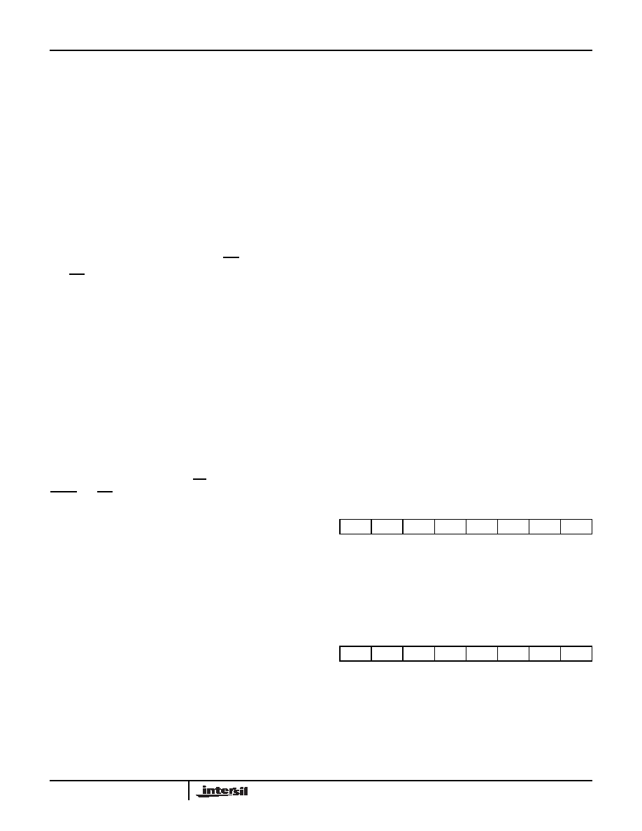
Register Descriptions
TABLE 1. DATA REGISTERS, (6-BIT), NONVOLATILE
There are four 6-bit Data Registers associated with the
potentiometer.
{D5~D0}: These bits are for general purpose Nonvolatile
data storage or for storage of up to four different wiper
values.
TABLE 2. WIPER COUNTER REGISTER, (6-BIT), VOLATILE
{WP5~WP0}: These bits specify the wiper position of the
potentiometer.
0
D5
D4
D3
D2
D1
D0
(MSB)
(LSB)
0
WP5WP4
WP3WP2
WP1WP0
(MSB)
(LSB)
X9421
相关PDF资料 |
PDF描述 |
|---|---|
| X9421YV14IZ-2.7T1 | IC XDCP SGL 64-TAP 2.5K 14-TSSOP |
| M83723/85W20416 | CONN RCPT 41POS JAM NUT W/PINS |
| X9421YV14Z-2.7T1 | IC XDCP SGL 64-TAP 2.5K 14-TSSOP |
| GTC01A-14S-4S | CONN RCPT 1POS INLINE W/SCKT |
| MS3456L24-7S | CONN PLUG 16POS STRAIGHT W/SCKT |
相关代理商/技术参数 |
参数描述 |
|---|---|
| X9421YV14T1 | 功能描述:IC XDCP SGL 64-TAP 2.5K 14-TSSOP RoHS:否 类别:集成电路 (IC) >> 数据采集 - 数字电位器 系列:XDCP™ 产品培训模块:Lead (SnPb) Finish for COTS Obsolescence Mitigation Program 标准包装:2,500 系列:- 接片:32 电阻(欧姆):50k 电路数:1 温度系数:标准值 50 ppm/°C 存储器类型:易失 接口:3 线串行(芯片选择,递增,增/减) 电源电压:2.7 V ~ 5.5 V 工作温度:-40°C ~ 85°C 安装类型:表面贴装 封装/外壳:SOT-23-6 细型,TSOT-23-6 供应商设备封装:TSOT-23-6 包装:带卷 (TR) |
| X9421YV14Z | 功能描述:IC XDCP SGL 64-TAP 2.5K 14-TSSOP RoHS:是 类别:集成电路 (IC) >> 数据采集 - 数字电位器 系列:XDCP™ 产品培训模块:Lead (SnPb) Finish for COTS Obsolescence Mitigation Program 标准包装:2,500 系列:- 接片:32 电阻(欧姆):50k 电路数:1 温度系数:标准值 50 ppm/°C 存储器类型:易失 接口:3 线串行(芯片选择,递增,增/减) 电源电压:2.7 V ~ 5.5 V 工作温度:-40°C ~ 85°C 安装类型:表面贴装 封装/外壳:SOT-23-6 细型,TSOT-23-6 供应商设备封装:TSOT-23-6 包装:带卷 (TR) |
| X9421YV14Z-2.7 | 功能描述:IC XDCP SGL 64-TAP 2.5K 14-TSSOP RoHS:是 类别:集成电路 (IC) >> 数据采集 - 数字电位器 系列:XDCP™ 产品培训模块:Lead (SnPb) Finish for COTS Obsolescence Mitigation Program 标准包装:2,500 系列:- 接片:32 电阻(欧姆):50k 电路数:1 温度系数:标准值 50 ppm/°C 存储器类型:易失 接口:3 线串行(芯片选择,递增,增/减) 电源电压:2.7 V ~ 5.5 V 工作温度:-40°C ~ 85°C 安装类型:表面贴装 封装/外壳:SOT-23-6 细型,TSOT-23-6 供应商设备封装:TSOT-23-6 包装:带卷 (TR) |
| X9421YV14Z-2.7T1 | 功能描述:IC XDCP SGL 64-TAP 2.5K 14-TSSOP RoHS:是 类别:集成电路 (IC) >> 数据采集 - 数字电位器 系列:XDCP™ 产品培训模块:Lead (SnPb) Finish for COTS Obsolescence Mitigation Program 标准包装:2,500 系列:- 接片:32 电阻(欧姆):50k 电路数:1 温度系数:标准值 50 ppm/°C 存储器类型:易失 接口:3 线串行(芯片选择,递增,增/减) 电源电压:2.7 V ~ 5.5 V 工作温度:-40°C ~ 85°C 安装类型:表面贴装 封装/外壳:SOT-23-6 细型,TSOT-23-6 供应商设备封装:TSOT-23-6 包装:带卷 (TR) |
| X9421YV14ZT1 | 功能描述:IC XDCP SGL 64-TAP 2.5K 14-TSSOP RoHS:是 类别:集成电路 (IC) >> 数据采集 - 数字电位器 系列:XDCP™ 产品培训模块:Lead (SnPb) Finish for COTS Obsolescence Mitigation Program 标准包装:2,500 系列:- 接片:32 电阻(欧姆):50k 电路数:1 温度系数:标准值 50 ppm/°C 存储器类型:易失 接口:3 线串行(芯片选择,递增,增/减) 电源电压:2.7 V ~ 5.5 V 工作温度:-40°C ~ 85°C 安装类型:表面贴装 封装/外壳:SOT-23-6 细型,TSOT-23-6 供应商设备封装:TSOT-23-6 包装:带卷 (TR) |
发布紧急采购,3分钟左右您将得到回复。