- 您现在的位置:买卖IC网 > PDF目录16555 > XR16M681IL32-0C-EB (Exar Corporation)EVAL BOARD FOR XR16M681-C 32QFN PDF资料下载
参数资料
| 型号: | XR16M681IL32-0C-EB |
| 厂商: | Exar Corporation |
| 文件页数: | 10/51页 |
| 文件大小: | 0K |
| 描述: | EVAL BOARD FOR XR16M681-C 32QFN |
| 标准包装: | 1 |
| 系列: | * |
第1页第2页第3页第4页第5页第6页第7页第8页第9页当前第10页第11页第12页第13页第14页第15页第16页第17页第18页第19页第20页第21页第22页第23页第24页第25页第26页第27页第28页第29页第30页第31页第32页第33页第34页第35页第36页第37页第38页第39页第40页第41页第42页第43页第44页第45页第46页第47页第48页第49页第50页第51页
XR16M681
18
1.62V TO 3.63V UART WITH 32-BYTE FIFO AND VLIO INTERFACE
REV. 1.0.1
2.13
Auto Xon/Xoff (Software) Flow Control
When software flow control is enabled (See Table 15), the M681 compares one or two sequential receive data
characters with the programmed Xon or Xoff-1,2 character value(s). If receive character(s) (RX) match the
programmed values, the M681 will halt transmission (TX) as soon as the current character has completed
transmission. When a match occurs, the Xoff (if enabled via IER bit-5) flag will be set and the interrupt output
pin will be activated. Following a suspension due to a match of the Xoff character, the M681 will monitor the
receive data stream for a match to the Xon-1,2 character. If a match is found, the M681 will resume operation
and clear the flags (ISR bit-4).
Reset initially sets the contents of the Xon/Xoff 8-bit flow control registers to a logic 0. Following reset the user
can write any Xon/Xoff value desired for software flow control. Different conditions can be set to detect Xon/
Xoff characters (See Table 15) and suspend/resume transmissions. When double 8-bit Xon/Xoff characters
are selected, the M681 compares two consecutive receive characters with two software flow control 8-bit
values (Xon1, Xon2, Xoff1, Xoff2) and controls TX transmissions accordingly. Under the above described flow
control mechanisms, flow control characters are not placed (stacked) in the user accessible RX data buffer or
FIFO.
In the event that the receive buffer is overfilling and flow control needs to be executed, the M681 automatically
sends an Xoff message (when enabled) via the serial TX output to the remote modem. The M681 sends the
Xoff-1,2 characters two-character-times (= time taken to send two characters at the programmed baud rate)
after the receive FIFO crosses the programmed trigger level. To clear this condition, the M681 will transmit the
programmed Xon-1,2 characters as soon as receive FIFO is less than one trigger level below the programmed
trigger level. Table 5 below explains this.
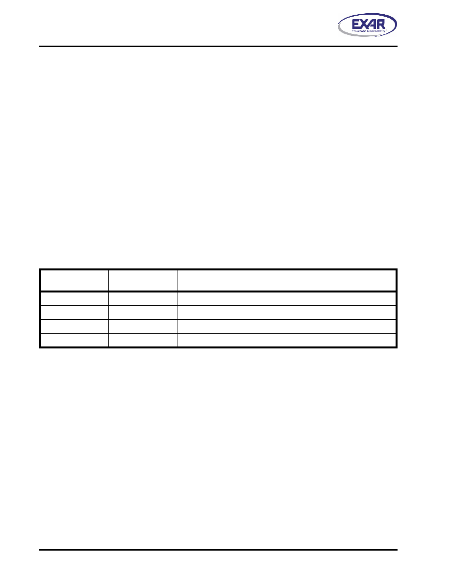
TABLE 5: AUTO XON/XOFF (SOFTWARE) FLOW CONTROL
RX TRIGGER LEVEL
INT PIN ACTIVATION
XOFF CHARACTER(S) SENT
(CHARACTERS IN RX FIFO)
XON CHARACTER(S) SENT
(CHARACTERS IN RX FIFO)
8
8*
0
16
16*
8
24
24*
16
28
28*
24
* After the trigger level is reached, an xoff character is sent after a short span of time (= time required to send 2 characters);
for example, after 2.083ms has elapsed for 9600 baud and 10-bit word length setting.
2.14
Special Character Detect
A special character detect feature is provided to detect an 8-bit character when bit-5 is set in the Enhanced
Feature Register (EFR). When this character (Xoff2) is detected, it will be placed in the FIFO along with normal
incoming RX data.
The M681 compares each incoming receive character with Xoff-2 data. If a match exists, the received data will
be transferred to the RX FIFO and ISR bit-4 will be set to indicate detection of special character. Although the
Internal Register Table shows Xon, Xoff Registers with eight bits of character information, the actual number of
bits is dependent on the programmed word length. Line Control Register (LCR) bits 0-1 defines the number of
character bits, i.e., either 5 bits, 6 bits, 7 bits, or 8 bits. The word length selected by LCR bits 0-1 also
determines the number of bits that will be used for the special character comparison. Bit-0 in the Xon, Xoff
Registers corresponds with the LSB bit for the receive character.
2.15
Normal Multidrop Mode
Normal multidrop mode is enabled when MSR[6] = 1 (requires EFR[4] = 1) and EFR[5] = 0 (Special Character
Detect disabled). The receiver is set to Force Parity 0 (LCR[5:3] = ’111’) in order to detect address bytes.
With the receiver initially disabled, it ignores all the data bytes (parity bit = 0) until an address byte is received
(parity bit = 1). This address byte will cause the UART to set the parity error. The UART will generate an LSR
相关PDF资料 |
PDF描述 |
|---|---|
| H3CWH-2618G | IDC CABLE - HKC26H/AE26G/HPL26H |
| EMM12DRSS | CONN EDGECARD 24POS DIP .156 SLD |
| MAX8662ETM+T | IC PMIC LI+ SNGL CELL 48TQFN |
| H3AWH-3406M | IDC CABLE - HSC34H/AE34M/HPL34H |
| H3CKH-3406M | IDC CABLE - HKC34H/AE34M/HPK34H |
相关代理商/技术参数 |
参数描述 |
|---|---|
| XR16M681IL32-F | 功能描述:UART 接口集成电路 1.62-3.63V; 32-Byte FIFO & VLIO; UART RoHS:否 制造商:Texas Instruments 通道数量:2 数据速率:3 Mbps 电源电压-最大:3.6 V 电源电压-最小:2.7 V 电源电流:20 mA 最大工作温度:+ 85 C 最小工作温度:- 40 C 封装 / 箱体:LQFP-48 封装:Reel |
| XR16M698 | 制造商:EXAR 制造商全称:EXAR 功能描述:1.62V TO 3.63V HIGH PERFORMANCE OCTAL UART WITH 32-BYTE FIFO |
| XR16M698IQ-0A-EVB | 功能描述:界面开发工具 Eval Board for XR16M698IQ-0A RoHS:否 制造商:Bourns 产品:Evaluation Boards 类型:RS-485 工具用于评估:ADM3485E 接口类型:RS-485 工作电源电压:3.3 V |
| XR16M698IQ-0B-EVB | 功能描述:界面开发工具 Eval Board for XR16M698IQ-0B RoHS:否 制造商:Bourns 产品:Evaluation Boards 类型:RS-485 工具用于评估:ADM3485E 接口类型:RS-485 工作电源电压:3.3 V |
| XR16M698IQ100 | 制造商:EXAR 制造商全称:EXAR 功能描述:1.62V TO 3.63V HIGH PERFORMANCE OCTAL UART WITH 32-BYTE FIFO |
发布紧急采购,3分钟左右您将得到回复。