- 您现在的位置:买卖IC网 > PDF目录16425 > XR17C158CV-0A-EVB (Exar Corporation)EVAL BOARD FOR XR17C158-A 144TQF PDF资料下载
参数资料
| 型号: | XR17C158CV-0A-EVB |
| 厂商: | Exar Corporation |
| 文件页数: | 7/67页 |
| 文件大小: | 0K |
| 描述: | EVAL BOARD FOR XR17C158-A 144TQF |
| 标准包装: | 1 |
| 系列: | * |
第1页第2页第3页第4页第5页第6页当前第7页第8页第9页第10页第11页第12页第13页第14页第15页第16页第17页第18页第19页第20页第21页第22页第23页第24页第25页第26页第27页第28页第29页第30页第31页第32页第33页第34页第35页第36页第37页第38页第39页第40页第41页第42页第43页第44页第45页第46页第47页第48页第49页第50页第51页第52页第53页第54页第55页第56页第57页第58页第59页第60页第61页第62页第63页第64页第65页第66页第67页
xr
XR17C158
REV. 1.4.3
5V PCI BUS OCTAL UART
15
1.2.1
The Interrupt Status Register
The XR17C158 has a 32-bit wide register [INT0, INT1, INT2 and INT3] to provide interrupt information and
supports two interrupt schemes. The first scheme is an 8-bit indicator representing all 8 channels with each bit
representing each channel from 0 to 7. This permits the interrupt routine to quickly vector and serve that UART
channel and determine the source(s) in each individual routines. INT0 bit-0 represents the interrupt status for
UART channel 0 when its transmitter, receiver, line status, or modem port status requires service. Other bits in
the INT0 register provide indication for the other channels with bit-7 representing UART channel 7 respectively.
The second scheme provides detail about the source of the interrupts for each UART channel. All the interrupts
are encoded into a 3-bit code. This 3-bit code represents 7 interrupts corresponding to individual UART’s
transmitter, receiver, line status, modem port status. INT1, INT2 and INT3 registers provide the 24-bit interrupt
status for all 8 channels. Bits 8, 9 and 10 representing channel 0 and bits 29, 30 and 31 representing channel 7
respectively. All 8 channel interrupts status are available with a single DWORD read operation. This feature
allows the host to quickly vector and serve the interrupts, reducing service interval, hence, reducing the host
bandwidth requirement. Figure 4 shows the 4-byte interrupt register and its make up.
A special interrupt condition is generated by the 158 when it wakes up from sleep mode. This special interrupt
is cleared by reading the INT0 register. If there are not any other interrupts pending, the value read from INT0
would be 0x00.
INT0 [7:0] Channel Interrupt Indicator
Each bit gives an indication of the channel that has requested for service. Bit-0 represents channel 0 and bit-7
indicates channel 7. Logic 1 indicates that a channel has called for service. The interrupt bit clears after
reading the appropriate register of the interrupting channel register, see Interrupt Clearing section.
INT3, INT2 and INT1 [32:8]
Twenty four bit encoded interrupt indicator. Each channel’s interrupt is encoded into 3 bits for receive, transmit,
and status. Bits [10:8] represent channel 0 and go up to channel 7 with bits [31:29]. The 3 bit encoding and
their priority order are shown below in Table 5. The Timer and MPIO interrupts are for the device and therefore
they only exist within the channel 0 space (bits [10:8]) and not in any other channel.
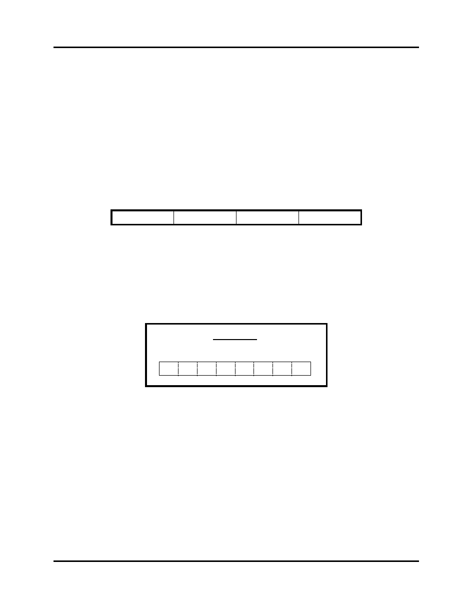
GLOBAL INTERRUPT REGISTER (DWORD)
[default 0x00-00-00-00]
INT3 [31:24]
INT2 [23:16]
INT1 [15:8]
INT0 [7:0]
The INT0 register provides individual status for each channel
INT0 Register
Individual UART Channel Interrupt Status
Ch-6
Ch-7
Ch-5 Ch-4 Ch-3 Ch-2 Ch-1 Ch-0
Bit-7 Bit-6 Bit-5 Bit-4 Bit-3 Bit-2 Bit-1 Bit-0
相关PDF资料 |
PDF描述 |
|---|---|
| SK221M025ST | CAP ALUM 220UF 25V 20% RADIAL |
| M3TTK-1436J | IDC CABLE - MSD14K/MC14G/MSD14K |
| CDB42L51 | BOARD EVAL FOR CS42L51 CODEC |
| GMM11DRKI | CONN EDGECARD 22POS DIP .156 SLD |
| UPJ1J151MHD6TO | CAP ALUM 150UF 63V 20% RADIAL |
相关代理商/技术参数 |
参数描述 |
|---|---|
| XR17C158CV-F | 功能描述:UART 接口集成电路 UART RoHS:否 制造商:Texas Instruments 通道数量:2 数据速率:3 Mbps 电源电压-最大:3.6 V 电源电压-最小:2.7 V 电源电流:20 mA 最大工作温度:+ 85 C 最小工作温度:- 40 C 封装 / 箱体:LQFP-48 封装:Reel |
| XR17C158CVTR-F | 制造商:Exar Corporation 功能描述:UART 8-CH 64Byte FIFO 5V 144-Pin LQFP T/R 制造商:Exar Corporation 功能描述:XR17C158CVTR-F |
| XR17C158IV | 功能描述:UART 接口集成电路 UART RoHS:否 制造商:Texas Instruments 通道数量:2 数据速率:3 Mbps 电源电压-最大:3.6 V 电源电压-最小:2.7 V 电源电流:20 mA 最大工作温度:+ 85 C 最小工作温度:- 40 C 封装 / 箱体:LQFP-48 封装:Reel |
| XR17C158IV-F | 功能描述:UART 接口集成电路 UART RoHS:否 制造商:Texas Instruments 通道数量:2 数据速率:3 Mbps 电源电压-最大:3.6 V 电源电压-最小:2.7 V 电源电流:20 mA 最大工作温度:+ 85 C 最小工作温度:- 40 C 封装 / 箱体:LQFP-48 封装:Reel |
| XR17C158IVTR-F | 制造商:Exar Corporation 功能描述:UART 8-CH 64Byte FIFO 5V 144-Pin LQFP T/R 制造商:Exar Corporation 功能描述:XR17C158IVTR-F |
发布紧急采购,3分钟左右您将得到回复。