参数资料
| 型号: | XR21V1414IM48-F |
| 厂商: | Exar Corporation |
| 文件页数: | 31/34页 |
| 文件大小: | 0K |
| 描述: | IC UART FIFO USB QUAD 48TQFP |
| 产品培训模块: | UART Product Overview XR21V141x Full-Speed USB UART Family |
| 特色产品: | XR21V141x Full-Speed USB UART |
| 标准包装: | 250 |
| 特点: | * |
| 通道数: | 1,UART |
| FIFO's: | 128 字节 |
| 规程: | USB 2.0 |
| 电源电压: | 3.3V |
| 带自动流量控制功能: | 是 |
| 安装类型: | 表面贴装 |
| 封装/外壳: | 48-TQFP |
| 供应商设备封装: | 48-TQFP(7x7) |
| 包装: | 托盘 |
| 配用: | 1016-1303-ND - EVAL BOARD FOR XR21V1414IM |
| 其它名称: | 1016-1304 |
第1页第2页第3页第4页第5页第6页第7页第8页第9页第10页第11页第12页第13页第14页第15页第16页第17页第18页第19页第20页第21页第22页第23页第24页第25页第26页第27页第28页第29页第30页当前第31页第32页第33页第34页
XR21V1414
6
4-CH FULL-SPEED USB UART
REV. 1.3.0
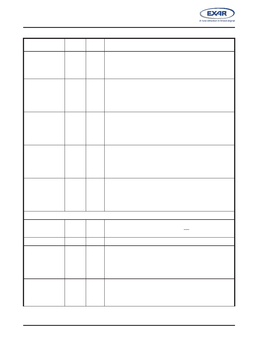
GPIOC1/CDC#
28
I/O
UART Channel C general purpose I/O or UART Carrier-Detect input
(active low). This pin has an internal pull-up resistor which is disabled dur-
ing suspend mode. If using this GPIO as an input, an external pull-up
resistor is required to minimize the power consumption in the suspend
mode.
GPIOC2/DSRC#
27
I/O
UART Channel C general purpose I/O or UART Data-Set-Ready input
(active low).
See ”Section 1.5.6, Automatic DTR/DSR Hardware
Flow Control” on page 13. This pin has an internal pull-up resistor
which is disabled during suspend mode. If using this GPIO as an input, an
external pull-up resistor is required to minimize the power consumption in
the suspend mode.
GPIOC3/DTRC#
26
I/O
UART Channel C general purpose I/O or UART Data-Terminal-Ready out-
put (active low).
See ”Section 1.5.6, Automatic DTR/DSR Hard-
ware Flow Control” on page 13. This pin has an internal pull-up
resistor which is disabled during suspend mode. If using this GPIO as an
input, an external pull-up resistor is required to minimize the power con-
sumption in the suspend mode.
GPIOC4/CTSC#
25
I/O
UART Channel C general purpose I/O or UART Clear-to-Send input
(active low).
See ”Section 1.5.5, Automatic RTS/CTS Hardware
Flow Control” on page 13. This pin has an internal pull-up resistor
which is disabled during suspend mode. If using this GPIO as an input, an
external pull-up resistor is required to minimize the power consumption in
the suspend mode.
GPIOC5/RTSC#/
RS485C
24
I/O
UART Channel C general purpose I/O or UART Request-to-Send output
(active low) or auto RS-485 half-duplex control.
See ”Section 1.5.5,
Automatic RTS/CTS Hardware Flow Control” on page 13. This
pin has an internal pull-up resistor which is disabled during suspend mode.
If using this GPIO as an input, an external pull-up resistor is required to
minimize the power consumption in the suspend mode.
UART Channel D Signals
RXD
39
I
UART Channel D Receive Data or IR Receive Data. This pin has an inter-
nal pull-up resistor. Internal pull-up resistor is not disabled during suspend
mode.
TXD
38
O
UART Channel D Transmit Data or IR Transmit Data.
GPIOD0/RID#/
RWKD#
37
I/O
UART Channel D general purpose I/O or UART Ring-Indicator input
(active low) or Remote Wakeup Input (
See ”Section 1.5.12, USB Sus-
pend” on page 14.). This pin has an internal pull-up resistor which is
disabled during suspend mode. If using this GPIO as an input, an external
pull-up resistor is required to minimize the power consumption in the sus-
pend mode.
GPIOD1/CDD#
34
I/O
UART Channel D general purpose I/O or UART Carrier-Detect input
(active low). This pin has an internal pull-up resistor which is disabled dur-
ing suspend mode. If using this GPIO as an input, an external pull-up
resistor is required to minimize the power consumption in the suspend
mode.
Pin Description
NAME
48-QFN
PIN #
TYPE
DESCRIPTION
相关PDF资料 |
PDF描述 |
|---|---|
| XR3178EID-F | IC TXRX RS485 DIFF 3V 8NSOIC |
| XR5488EID-F | IC TXRX RS485 PROFIBUS 8NSOIC |
| XR68C681P-F | IC UART CMOS DUAL 40PDIP |
| XR68C92CJ-F | IC UART FIFO DUAL 44PLCC |
| XR68M752IB49-F | IC UART FIFO 64B DUAL 49STBGA |
相关代理商/技术参数 |
参数描述 |
|---|---|
| XR21V1414IM48-F | 制造商:Exar Corporation 功能描述:IC QUAD UART 12MBPS 3.63V 48-TQFP |
| XR21V1414IM48TR-F | 制造商:Exar Corporation 功能描述:USB-to-UART 4-CH 128Byte FIFO 48-Pin TQFP T/R 制造商:Exar Corporation 功能描述:XR21V1414 Series 12 Mbps 3.63 V Quad Channel USB UART SMT - TQFP-48 制造商:Exar Corporation 功能描述:XR21V1414IM48TR-F 制造商:EXAR 功能描述:USB-to-UART 4-CH 128Byte FIFO 48-Pin TQFP T/R |
| XR21V1414M48-F | 制造商:Exar Corporation 功能描述:UART 4-CH FULL SPEED USB I/F 48TQFP 制造商:Exar Corporation 功能描述:UART, 4-CH FULL SPEED, USB I/F, 48TQFP, No. of Channels:4, Data Rate:12Mbps, Sup |
| XR-2200CP | 制造商:未知厂家 制造商全称:未知厂家 功能描述:PERIPHERAL DRIVER|5 DRIVER|DIP|14PIN|PLASTIC |
| XR-2201CP | 制造商:未知厂家 制造商全称:未知厂家 功能描述:Septuple Peripheral Driver |
发布紧急采购,3分钟左右您将得到回复。