- 您现在的位置:买卖IC网 > PDF目录11650 > XTR112UA/2K5 (Texas Instruments)IC 4-20MA I-TRANSMITTER 14-SOIC PDF资料下载
参数资料
| 型号: | XTR112UA/2K5 |
| 厂商: | Texas Instruments |
| 文件页数: | 6/18页 |
| 文件大小: | 0K |
| 描述: | IC 4-20MA I-TRANSMITTER 14-SOIC |
| 标准包装: | 2,500 |
| 类型: | 电流发送器 |
| 输入类型: | 电压 |
| 输出类型: | 电压 |
| 接口: | 2 线 |
| 电流 - 电源: | 20mA |
| 安装类型: | 表面贴装 |
| 封装/外壳: | 14-SOIC(0.154",3.90mm 宽) |
| 供应商设备封装: | 14-SOIC |
| 包装: | 带卷 (TR) |
14
XTR112, XTR114
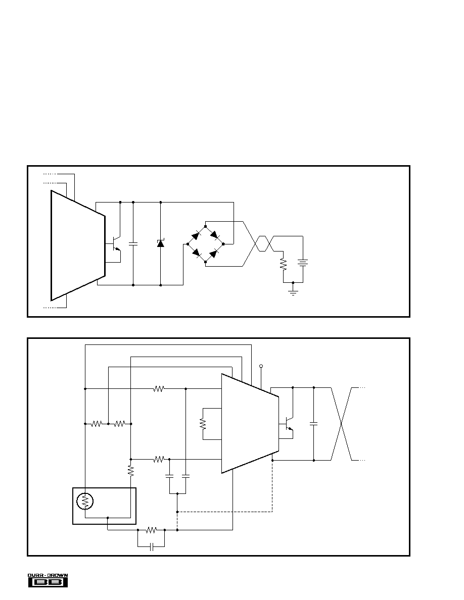
FIGURE 5. Input Bypassing Technique with Linearization.
14
11
12
13
4
3
2
R
G
XTR112
XTR114
R
CM
7
1
0.01
F
0.01
F
0.01
F
R
Z
(1)
RTD
6
NOTE: (1) Bypass capacitors can be connected
to either the I
RET pin or the IO pin.
R
G
R
G
V
IN
–
V
IN
+
V
LIN I
R1
I
R2
V
REG
V+
I
RET
I
O
E
B
8
0.01
F
9
10
1k
R
LIN1
R
LIN2
1k
XTR112
XTR114
7
V+
I
O
E
B
V
PS
10
0.01
F
R
L
D
1
(1)
9
8
NOTE: (1) Zener Diode 36V: 1N4753A or General
Semiconductor TransorbTM 1N6286A. Use lower
voltage zener diodes with loop power supply
voltages less than 30V for increased protection.
See “Over-Voltage Surge Protection.”
Maximum V
PS must be
less
than
minimum
voltage rating of zener
diode.
The diode bridge causes
a 1.4V loss in loop supply
voltage.
1N4148
Diodes
6
I
RET
FIGURE 4. Reverse Voltage Operation and Over-Voltage Surge Protection.
Most surge protection zener diodes have a diode character-
istic in the forward direction that will conduct excessive
current, possibly damaging receiving-side circuitry if the
loop connections are reversed. If a surge protection diode is
used, a series diode or diode bridge should be used for
protection against reversed connections.
RADIO FREQUENCY INTERFERENCE
The long wire lengths of current loops invite radio frequency
interference. RF can be rectified by the sensitive input
circuitry of the XTR112 and XTR114 causing errors. This
generally appears as an unstable output current that varies
with the position of loop supply or input wiring.
If the RTD sensor is remotely located, the interference may
enter at the input terminals. For integrated transmitter as-
semblies with short connection to the sensor, the interfer-
ence more likely comes from the current loop connections.
Bypass capacitors on the input reduce or eliminate this input
interference. Connect these bypass capacitors to the IRET
terminal as shown in Figure 5. Although the dc voltage at the
IRET terminal is not equal to 0V (at the loop supply, VPS) this
circuit point can be considered the transmitter’s “ground.”
The 0.01
F capacitor connected between V+ and I
O may
help minimize output interference.
相关PDF资料 |
PDF描述 |
|---|---|
| MC9S12XA256CAA | IC MCU 256K FLASH 80-QFP |
| MC9S12B64MPVE | IC MCU 64K FLASH 25MHZ 112-LQFP |
| D38999/20FJ24PN | CONN RCPT 24POS WALL MNT W/PINS |
| MC9S12E128MFUE | IC MCU 128K FLASH 25MHZ 80-QFP |
| MS3101A36-52S | CONN RCPT 52POS FREE HNG W/SCKT |
相关代理商/技术参数 |
参数描述 |
|---|---|
| XTR112UAE4 | 功能描述:电流灵敏放大器 4-20mA Crnt Trnsmtr w/Sensor Exc & Lin RoHS:否 制造商:Texas Instruments 通道数量: 共模抑制比(最小值):110 dB 输入补偿电压:80 uV 电源电压-最大:5.5 V 电源电压-最小:2.7 V 电源电流:350 uA 最大工作温度:+ 125 C 最小工作温度:- 40 C 安装风格:SMD/SMT 封装 / 箱体:VQFN-16 封装:Reel |
| XTR112UE4 | 功能描述:电流灵敏放大器 4-20mA Crnt Trnsmtr w/Sensor Exc & Lin RoHS:否 制造商:Texas Instruments 通道数量: 共模抑制比(最小值):110 dB 输入补偿电压:80 uV 电源电压-最大:5.5 V 电源电压-最小:2.7 V 电源电流:350 uA 最大工作温度:+ 125 C 最小工作温度:- 40 C 安装风格:SMD/SMT 封装 / 箱体:VQFN-16 封装:Reel |
| XTR114 | 制造商:BB 制造商全称:BB 功能描述:4-20mA CURRENT TRANSMITTERS with Sensor Excitation and Linearization |
| XTR114U | 功能描述:电流灵敏放大器 4-20mA Crnt Trnsmtr w/Sensor Exc & Lin RoHS:否 制造商:Texas Instruments 通道数量: 共模抑制比(最小值):110 dB 输入补偿电压:80 uV 电源电压-最大:5.5 V 电源电压-最小:2.7 V 电源电流:350 uA 最大工作温度:+ 125 C 最小工作温度:- 40 C 安装风格:SMD/SMT 封装 / 箱体:VQFN-16 封装:Reel |
| XTR114U/2K5 | 功能描述:IC 4-20MA I-TRANSMITTER 14-SOIC RoHS:是 类别:集成电路 (IC) >> 接口 - 传感器和探测器接口 系列:- 其它有关文件:Automotive Product Guide 产品培训模块:Lead (SnPb) Finish for COTS Obsolescence Mitigation Program 标准包装:74 系列:- 类型:触控式传感器 输入类型:数字 输出类型:数字 接口:JTAG,串行 电流 - 电源:100µA 安装类型:表面贴装 封装/外壳:20-TSSOP(0.173",4.40mm 宽) 供应商设备封装:20-TSSOP 包装:管件 |
发布紧急采购,3分钟左右您将得到回复。