- 您现在的位置:买卖IC网 > PDF目录11676 > XTR114U (Texas Instruments)IC 4-20MA TRANSMITTER 14-SOIC PDF资料下载
参数资料
| 型号: | XTR114U |
| 厂商: | Texas Instruments |
| 文件页数: | 2/18页 |
| 文件大小: | 0K |
| 描述: | IC 4-20MA TRANSMITTER 14-SOIC |
| 标准包装: | 50 |
| 类型: | 电流发送器 |
| 输入类型: | 电压 |
| 输出类型: | 电压 |
| 接口: | 2 线 |
| 电流 - 电源: | 20mA |
| 安装类型: | 表面贴装 |
| 封装/外壳: | 14-SOIC(0.154",3.90mm 宽) |
| 供应商设备封装: | 14-SO |
| 包装: | 管件 |
| 产品目录页面: | 904 (CN2011-ZH PDF) |
10
XTR112, XTR114
R2 = RTD resistance at maximum measured temperature, T
MAX
where RZ = RTD resistance at the minimum measured temperature, T
MIN
RLIN = 1k (internal)
XTR112 RESISTOR EXAMPLE:
The measurement range is –100
°C to +200°C for a 3-wire Pt100 RTD connection. Determine the values for R
S, RG, RLIN1, and RLIN2. Look up the values
from the chart or calculate the values according to the equations provided.
METHOD 1: TABLE LOOK UP
TMIN = –100°C and T = 300°C (TMAX = +200°C),
Using Table II the 1% values are:
RZ = 604
RLIN1 = 33.2k
RG = 750
RLIN2 = 59k
METHOD 2: CALCULATION
Step 1: Determine RZ, R1, and R2.
RZ is the RTD resistance at the minimum measured temperature, TMIN = –100°C.
Using Equation (1) at right gives RZ = 602.5 (1% value is 604).
R2 is the RTD resistance at the maximum measured temperature, TMAX = 200°C.
Using Equation (2) at right gives R2 = 1758.4.
R1 is the RTD resistance at the midpoint measured temperature,
TMID = (TMIN + TMAX) /2 = (–100 + 200)/2 = 50°C. R1 is NOT the average of RZ and R2.
Using Equation (2) at right gives R1 = 1194.
Step 2: Calculate RG, RLIN1, and RLIN2 using equations above.
RG = 757 (1% value is 750)
RLIN1 = 33.322k (1% value is 33.2k)
RLIN2 = 58.548k (1% value is 59k)
Calculation of Pt1000 Resistance Values
(according to DIN IEC 751)
Equation (1) Temperature range from –200
°C to 0°C:
R(T) = 1000 [1 + 3.90802 10–3 T – 0.5802 10–6 T2
– 4.27350 10–12 (T – 100) T3]
Equation (2) Temperature range from 0
°C to +850°C:
R(T) = 1000 (1 + 3.90802 10–3 T – 0.5802 10–6 T2)
where: R(T) is the resistance in at temperature T.
T is the temperature in
°C.
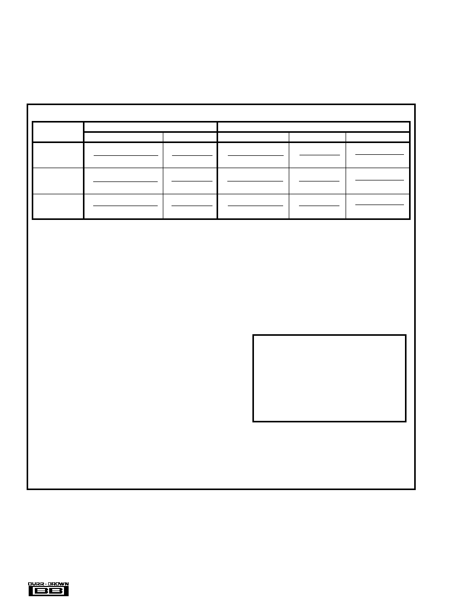
TABLE I. Summary of Resistor Equations for Two-Wire and Three-Wire Pt1000 RTD Connections.
Table I summarizes the resistor equations for two-wire and
three-wire RTD connections. An example calculation is also
provided. To maintain good accuracy, at least 1% (or better)
resistors should be used for RG. Table II provides standard
1% RG values for a three-wire Pt1000 RTD connection with
linearization for the XTR112. Table III gives RG values for
the XTR114.
LINEARIZATION
RTD temperature sensors are inherently (but predictably)
nonlinear. With the addition of one or two external resistors,
RLIN1 and RLIN2, it is possible to compensate for most of this
nonlinearity resulting in 40:1 improvement in linearity over
the uncompensated output.
General Equations
NOTE: Most RTD manufacturers provide reference tables for
resistance values at various temperatures.
Resistor values for other RTD types (such as Pt2000) can be
calculated using the XTR resistor selection program in the
Applications Section on Burr-Brown’s web site (www.burr-
brown.com)
IREF 2.5 [R1 (R2 + RZ) – 2 (R2RZ)]
(R2 – R1)
=
0.4 RLIN (R2 – R1)
IREF (2R1 – R2 – RZ)
=
IREF 2.5 (R2 – RZ) (R1 – RZ)]
(R2 – R1)
=
0.4 RLIN (R2 – R1)
IREF (2R1 – R2 – RZ)
=
0.4 (RLIN + RG)(R2 – R1)
IREF (2R1 – R2 – RZ)
=
XTR112 (IREF = 0.25)
(see Table II)
RG
RLIN1
RG
RLIN1
RLIN2
THREE-WIRE
TWO-WIRE
0.625 [R1 (R2 + RZ) – 2 (R2RZ)]
(R2 – R1)
=
1.6 RLIN (R2 – R1)
(2R1 – R2 – RZ)
=
0.625 (R2 – RZ) (R1 – RZ)]
(R2 – R1)
=
1.6 RLIN (R2 – R1)
(2R1 – R2 – RZ)
=
1.6 (RLIN + RG)(R2 – R1)
(2R1 – R2 – RZ)
=
0.25 [R1 (R2 + RZ) – 2 (R2RZ)]
(R2 – R1)
=
4 RLIN (R2 – R1)
(2R1 – R2 – RZ)
=
0.25 (R2 – RZ) (R1 – RZ)]
(R2 – R1)
=
4 RLIN (R2 – R1)
(2R1 – R2 – RZ)
=
4 (RLIN + RG)(R2 – R1)
(2R1 – R2 – RZ)
=
XTR114 (IREF = 0.1)
(see Table III)
R1 = RTD resistance at the midpoint measured temperature, T
MID = (TMIN + TMAX)/2
相关PDF资料 |
PDF描述 |
|---|---|
| VE-J32-IY-F2 | CONVERTER MOD DC/DC 15V 50W |
| VE-J32-IY-F1 | CONVERTER MOD DC/DC 15V 50W |
| VE-B3L-CU-S | CONVERTER MOD DC/DC 28V 200W |
| XTR112UA | IC 4-20MA TRANSMITTER 14-SOIC |
| VE-B3K-CU-S | CONVERTER MOD DC/DC 40V 200W |
相关代理商/技术参数 |
参数描述 |
|---|---|
| XTR114U/2K5 | 功能描述:IC 4-20MA I-TRANSMITTER 14-SOIC RoHS:是 类别:集成电路 (IC) >> 接口 - 传感器和探测器接口 系列:- 其它有关文件:Automotive Product Guide 产品培训模块:Lead (SnPb) Finish for COTS Obsolescence Mitigation Program 标准包装:74 系列:- 类型:触控式传感器 输入类型:数字 输出类型:数字 接口:JTAG,串行 电流 - 电源:100µA 安装类型:表面贴装 封装/外壳:20-TSSOP(0.173",4.40mm 宽) 供应商设备封装:20-TSSOP 包装:管件 |
| XTR114UA | 功能描述:电流灵敏放大器 4-20mA Crnt Trnsmtr w/Sensor Exc & Lin RoHS:否 制造商:Texas Instruments 通道数量: 共模抑制比(最小值):110 dB 输入补偿电压:80 uV 电源电压-最大:5.5 V 电源电压-最小:2.7 V 电源电流:350 uA 最大工作温度:+ 125 C 最小工作温度:- 40 C 安装风格:SMD/SMT 封装 / 箱体:VQFN-16 封装:Reel |
| XTR114UA/2K5 | 功能描述:IC 4-20MA I-TRANSMITTER 14-SOIC RoHS:是 类别:集成电路 (IC) >> 接口 - 传感器和探测器接口 系列:- 其它有关文件:Automotive Product Guide 产品培训模块:Lead (SnPb) Finish for COTS Obsolescence Mitigation Program 标准包装:74 系列:- 类型:触控式传感器 输入类型:数字 输出类型:数字 接口:JTAG,串行 电流 - 电源:100µA 安装类型:表面贴装 封装/外壳:20-TSSOP(0.173",4.40mm 宽) 供应商设备封装:20-TSSOP 包装:管件 |
| XTR114UA/2K5E4 | 功能描述:电流灵敏放大器 4-20mA Crnt Trnsmtr w/Sensor Exc & Lin RoHS:否 制造商:Texas Instruments 通道数量: 共模抑制比(最小值):110 dB 输入补偿电压:80 uV 电源电压-最大:5.5 V 电源电压-最小:2.7 V 电源电流:350 uA 最大工作温度:+ 125 C 最小工作温度:- 40 C 安装风格:SMD/SMT 封装 / 箱体:VQFN-16 封装:Reel |
| XTR114UAE4 | 功能描述:电流灵敏放大器 4-20mA Crnt Trnsmtr w/Sensor Exc & Lin RoHS:否 制造商:Texas Instruments 通道数量: 共模抑制比(最小值):110 dB 输入补偿电压:80 uV 电源电压-最大:5.5 V 电源电压-最小:2.7 V 电源电流:350 uA 最大工作温度:+ 125 C 最小工作温度:- 40 C 安装风格:SMD/SMT 封装 / 箱体:VQFN-16 封装:Reel |
发布紧急采购,3分钟左右您将得到回复。