- 您现在的位置:买卖IC网 > PDF目录48084 > Y5117PC (POWER-ONE INC) 1-OUTPUT DC-DC REG PWR SUPPLY MODULE PDF资料下载
参数资料
| 型号: | Y5117PC |
| 厂商: | POWER-ONE INC |
| 元件分类: | 电源模块 |
| 英文描述: | 1-OUTPUT DC-DC REG PWR SUPPLY MODULE |
| 文件页数: | 7/17页 |
| 文件大小: | 389K |
| 代理商: | Y5117PC |
MCD10186 Rev. 1.0, 18-Jun-10
www.power-one.com
Page 15 of 17
Y5117 17A DC-DC POL Data Sheet
3.0V to 13.2V Input
0.7V to 3.63V Output
APPENDIX A.
Setup and use of evaluation board to test and
measure operation of
A1. Purpose
This procedure explains the requirements for the
proper handling, tup, and testing of the Y5117P, to
ensure the protection of the device.
A2. Overview
Certain conditions have to be met in order to test the
functionality of this device. The Y5117P data sheet
determines constraints, both temperature and power
limitations involved in the testing and operation of the
unit.
These limitations must not be exceeded.
Prolonged operation at elevated temperature or
elevated power output can result in the failure of the
device.
A3. References
All specifications are referenced against latest
revision of the data sheet.
A4. Procedure
A4.1 Test Equipment
Power supply should be capable of delivering a
minimum of 20A and have the overvoltage protection.
Loads must be 30A capable and operate at voltages
down to 0.5V. Lead length between power supply
and unit under test (UUT) and between UUT and
load must be minimized, <1m is recommended.
Additional input capacitance may be required under
specific conditions.
The amount of capacitance
required is a factor of input impedance, input voltage,
input voltage regulation, and output current.
A4.2 Connection of Test Equipment
Pgnd is the common device ground pin. The input
and output ground connections are connected to this
pin.
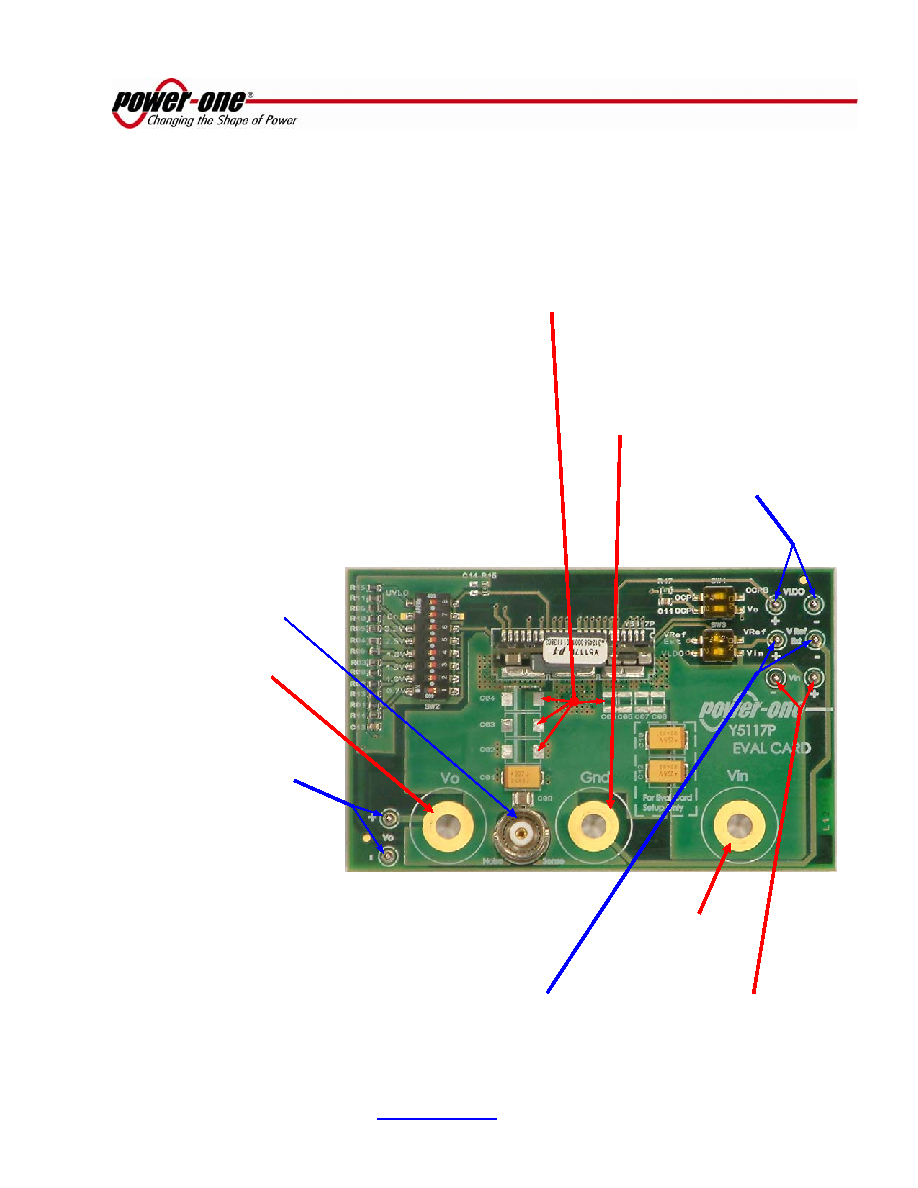
Optional
external
voltage
reference
input
(for
outputs
below 1.3V)
Optional components on
Y5117P evaluation card
VLDO
input
(for operation <5.2V)
Input voltage sense
measurements taken
from the input voltage
sense pins
The
output
ripple
measurements
are measured
using the 50 Ohms BNC
The
output
voltage
measurement is taken from the
output voltage sense
pins
The
positive
output
voltage
connections are
to this pin
The
positive
input
voltage
connection is to
this pin
The input and output
ground
connection is to
this pin
相关PDF资料 |
PDF描述 |
|---|---|
| Y5117P | 1-OUTPUT DC-DC REG PWR SUPPLY MODULE |
| Y5117P-G | 1-OUTPUT DC-DC REG PWR SUPPLY MODULE |
| Y802C04R | 10 A, 40 V, SILICON, RECTIFIER DIODE |
| Y802C09R | 10 A, 90 V, SILICON, RECTIFIER DIODE |
| Y97031 | Liquid Crystal Display Modules |
相关代理商/技术参数 |
参数描述 |
|---|---|
| Y5117PG-Q1 | 制造商:Power-One 功能描述:DCDC,HAZMAT - Bulk |
| Y5117PG-T1 | 制造商:Power-One 功能描述:DCDC,HAZMAT - Tape and Reel |
| Y5117PG-T2 | 制造商:Power-One 功能描述:DC/DC Power Supply Single-OUT 0.7V to 3.63V 17A 25-Pin SIP SMD T/R 制造商:Power-One 功能描述:DCDC,HAZMAT - Tape and Reel |
| Y5117PG-T3 | 制造商:Power-One 功能描述:- Tape and Reel |
| Y5117P-T2 | 制造商:Power-One 功能描述:Module DC-DC 1-OUT 0.7V to 3.63V 17A 25-Pin SIP SMD T/R |
发布紧急采购,3分钟左右您将得到回复。