- 您现在的位置:买卖IC网 > PDF目录48098 > YDA138-EZ 10 W, 2 CHANNEL, AUDIO AMPLIFIER, PDSO42 PDF资料下载
参数资料
| 型号: | YDA138-EZ |
| 元件分类: | 音频/视频放大 |
| 英文描述: | 10 W, 2 CHANNEL, AUDIO AMPLIFIER, PDSO42 |
| 封装: | LEAD FREE, PLASTIC, SSOP-42 |
| 文件页数: | 16/20页 |
| 文件大小: | 1198K |
| 代理商: | YDA138-EZ |
YDA138
5
■
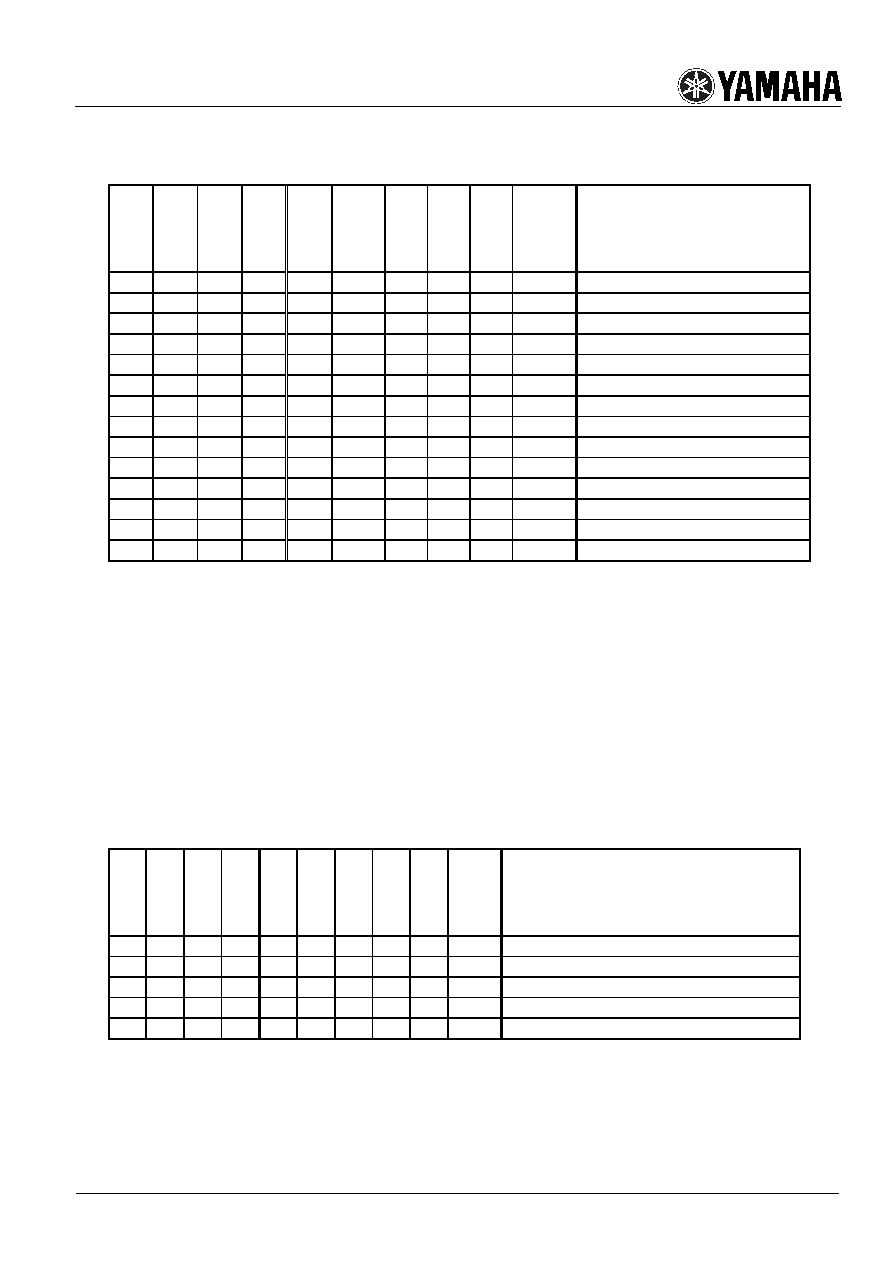
Mode setting
·
Operating Mode
SLEEPN
MUTEN
HP
MODE[2:0]
OUT*L
OUT*R
HPOL
HPOR
PROTN
CKIO
Outline
L
*
WL
Z
Sleep mode
H
L
*
WL
Z
-
DA Mute mode
*A)
H
L
H
*
WL
RF
Z
-
HA Mute mode
*A)
H
L
LLL
P-H
WL
Z
-
DA External Clock Slave mode
*A)
H
L
LLH
P-L
WL
Z
-
DA External Clock Slave mode
*A)
H
L
LHL
P-H
WL
Z
-
DA External Clock Master mode
*A)
H
L
LHH
P-L
WL
Z
-
DA External Clock Master mode
*A)
H
L
HLL
PLS
WL
Z
-
DA Internal Clock Slave mode
*A)
H
L
HHL
PLS
WL
Z
-
DA Internal Clock Master mode
*A)
H
*
WL
SIG
Z
-
HA mode
*A)
H
*
LL*
-
CKIN
4.19MHz Clock Input
H
*
LH*
-
CKOUT
4.19MHz Clock Output
H
*
HLL
-
CKIN
≒
500kHz Input (Internal Clock)
H
*
HHL
-
CKOUT
≒
500KHz Output (Internal Clock)
Note:
1) “H” and “L” means logic level High and logic level Low, respectively.
2) “WL” means output disabled (weak pull-down output). “RF” means reference level output. “Z” means Hi-Z.
3) “P-H” means a carrier clock of 524kHz. “P-L” means a carrier clock of 466kHz. “PLS” means a carrier clock of
approx. 500kHz (Internally generated clock).
4) “SIG” means an analog audio signal output.
5) “CKIN” means input of a clock with designated frequency. “CKOUT” means output of a designated clock.
6) “DA” means Digital Amplifier. “HA” means Headphone Amplifier.
7) Each output of OUT*L, OUT*R, HPOL, HPOR, PROTN, and CKIO becomes a state as shown in “Protection
Mode”, depending on the protection state, when entering protection state from a mode except sleep mode.
8) In monaural mode, OUT*R signal as shown in the above “Operating Mode” becomes the same as OUT*L signal.
And, HPOR becomes “WL.”
9) In operating modes indicated by *A), a state of the output signal becomes a state as shown in “Protection Mode”
during a protection mode.
10) “HLH” and “HHH” of MODE[2:0] is reserved for system use.
·
Protection Mode
SLEEPN
MUTEN
HP
MODE[2:0]
OUT*L
OUT*R
HPOL
HPOR
PROTN
CKIO
Outline
H
L
*
WL
L
Z
Digital Amplifier Over-current Protection
H
*
WL
L
Z
Over-Temperature Protection
H
*
WL
-
Clock Stop Protection
H
*
WL
Z
Low Voltage Malfunction Prevention Protection
H
*
WL
RF
-
Power Supply Voltage Fluctuation Protection
Note:
1) Each protection function operates when input terminal is in the designated logic condition. Output terminal
becomes a state as shown in the above during protection mode.
相关PDF资料 |
PDF描述 |
|---|---|
| YDA139-EZ | 2.5 W, 2 CHANNEL, AUDIO AMPLIFIER, PDSO24 |
| YDA139-WZ | 2.5 W, 2 CHANNEL, AUDIO AMPLIFIER, BGA25 |
| YDA142-EZ | 9.5 W, 2 CHANNEL, AUDIO AMPLIFIER, PDSO52 |
| YDA143-EZ | 15 W, 2 CHANNEL, AUDIO AMPLIFIER, PDSO52 |
| YDA144-QZ | 2.1 W, 2 CHANNEL, AUDIO AMPLIFIER, PQCC20 |
相关代理商/技术参数 |
参数描述 |
|---|---|
| YDA139 | 制造商:YAMAHA 制造商全称:YAMAHA CORPORATION 功能描述:D- 4 STEREO 2.5W DIGITAL AUDIO POWER AMPLIFIER |
| YDA142 | 制造商:YAMAHA 制造商全称:YAMAHA CORPORATION 功能描述:D- 3D DIGITAL INPUT STEREO 9.5W DIGITAL AUDIO POWER AMPLIFIER |
| YDA143 | 制造商:YAMAHA 制造商全称:YAMAHA CORPORATION 功能描述:D- 3M STEREO 15W DIGITAL AUDIO POWER AMPLIFIER |
| YDA144 | 制造商:YAMAHA 制造商全称:YAMAHA CORPORATION 功能描述:STEREO 2.1W Non-Clip DIGITAL AUDIO POWER AMPLIFIER |
| YDA148-QZ | 制造商:Yamaha Corp Of America 功能描述:STEREO 5W - 15W DIGITAL AUDIO POWER AMPLIFIER, QFN32 |
发布紧急采购,3分钟左右您将得到回复。