- 您现在的位置:买卖IC网 > PDF目录48110 > YV09T60-0EG (POWER-ONE INC) 1-OUTPUT DC-DC REG PWR SUPPLY MODULE PDF资料下载
参数资料
| 型号: | YV09T60-0EG |
| 厂商: | POWER-ONE INC |
| 元件分类: | 电源模块 |
| 英文描述: | 1-OUTPUT DC-DC REG PWR SUPPLY MODULE |
| 封装: | ROHS COMPLIANT, SIP-26 |
| 文件页数: | 3/14页 |
| 文件大小: | 302K |
| 代理商: | YV09T60-0EG |
YV09T60 60A DC-DC POL Converter
5V to 13.8V Input 0.6V to 3.63V Output
Data Sheet
ZD-01724 Rev 3.3, 30-Aug-10
www.power-one.com
Page 11 of 14
RTRIM = Required value of trim resistor in k
VOUT = Desired (trimmed) value of output voltage V
If the RTRIM is not used and the Sense+ and Sense-
pins are shorted to Vout and GND respectively, the
output voltage of the POL converter will be 0.6V. No
capacitor is allowed between Trim+ and Trim- pins.
Note that the trim resistor tolerance directly affects
the output voltage accuracy. It is recommended to
use ±0.1% trim resistors to meet the output voltage
setpoint accuracy specified in p. 4.2.
Table 1. Trim Resistor Values
V0UT, V
Calculated
RTRIM, k
Standard Value of
0.1% Resistor, k
0.6
Open
1.0
3.0
3.01
1.2
2.0
1.5
1.333
1.33
1.8
1.0
2.0
0.857
0.856
2.5
0.631
0.634
3.3
0.444
0.442
3.63
0.396
0.397
6.3
ON/OFF (Pin 9)
The ON/OFF pin is used to turn the POL converter
ON or OFF remotely by a signal from a system
controller. For positive logic, the POL converter is
ON when the ON/OFF pin is at a logic high (2.4V
min) or left open. The POL converter is OFF when
the ON/OFF pin is at a logic low (1.2V max) or
connected to GND.
The typical connections are shown in Figure 27.
Vin
CONTROL
INPUT
Vin
GND
ON/OFF
Converter
Vout
3,7,8
12,13,14
15,16,18,20,22,24
9
YV-Series
Power Good
4
TRIM+
1
SENSE+
11
Rload
GND
17,19,21,23
TRIM- 5
SENSE-
10
Figure 27. Circuit Configuration For ON/OFF Function
The ON/OFF pin is referenced to ground and
typically has 50k input impedance.
It has an
internal 50k pull-up to 5V supply.
It is
recommended to control the ON/OFF pin with an
open collector transistor or similar device.
6.4
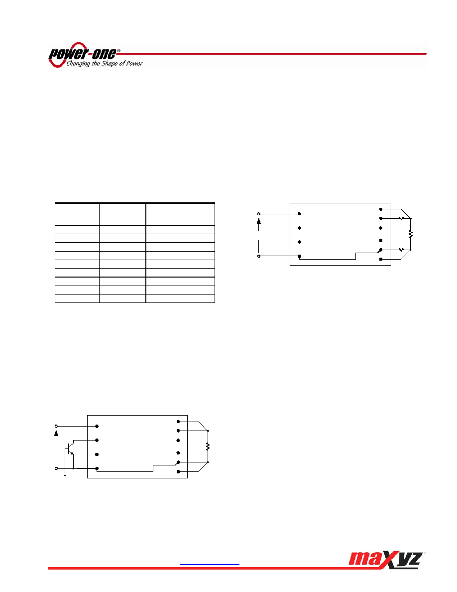
Remote Sense (Pins 10 and 11)
The remote sense feature compensates for the
voltage drop between the output pins of the POL
converter and the load. The Sense- (Pin 10) and
Sense+ (Pin 11) pins should be connected at the
load or at the point where regulation is required
(refer to Figure 28).
If remote sensing is not required, the Sense pins
must be connected to the Vout and GND pins
directly at the output of the POL converter.
Vin
GND
ON/OFF
Converter
Vout
3,7,8
12,13,14
15,16,18,20,22,24
9
YV-Series
Power Good
4
TRIM+
1
SENSE+
11
Rload
GND
17,19,21,23
TRIM- 5
SENSE-
10
Rw
Figure 28. Remote Sense Circuit Configuration
Because the sense leads carry minimal current,
large traces on the end-user board are not required.
The voltage sense traces should be located close to
a ground plane to minimize system noise.
When using remote sense, the output voltage at the
converter can be increased by up to 0.5V in order to
maintain the required voltage at the load. However,
the maximum output voltage measured directly
between the Vout and GND pins shall not exceed
3.63V. In addition it is the user’s responsibility to
ensure the POL converter’s actual output power
always remains at or below the maximum allowable
output power obtained from the derating curves.
6.5
Protections
6.5.1
Power Good
Power Good pin (Pin 4) is an open drain output,
capable of sinking up to 4mA. The Power Good pin
is high when the output voltage is within the
regulation band. The Power Good pin is at logic low
during
start-up,
undervoltage,
overvoltage
or
overcurrent conditions, or when the POL converter is
disabled via the ON/OFF signal.
6.5.2
Input Undervoltage Lockout
The POL converter will shut down when the input
voltage drops below a predetermined voltage. It will
相关PDF资料 |
PDF描述 |
|---|---|
| YV09T60-0E | 1-OUTPUT DC-DC REG PWR SUPPLY MODULE |
| YV12T25-0 | 1-OUTPUT DC-DC REG PWR SUPPLY MODULE |
| YV12T25-0G | 1-OUTPUT DC-DC REG PWR SUPPLY MODULE |
| YVZ152B-F | SPECIALTY CONSUMER CIRCUIT, PQFP64 |
| YVZ155 | SPECIALTY CONSUMER CIRCUIT, PQFP64 |
相关代理商/技术参数 |
参数描述 |
|---|---|
| YV09T60-0G | 功能描述:DC/DC转换器 0.6-3.63Vout 60A 5V-13.8VIn RoHS:否 制造商:Murata 产品: 输出功率: 输入电压范围:3.6 V to 5.5 V 输入电压(标称): 输出端数量:1 输出电压(通道 1):3.3 V 输出电流(通道 1):600 mA 输出电压(通道 2): 输出电流(通道 2): 安装风格:SMD/SMT 封装 / 箱体尺寸: |
| YV10X5R4A-2 | 制造商:Fujinon 功能描述:5-50mm Day/Night Varifocal Lens |
| YV10X5R4A-2L | 制造商:Fujinon 功能描述:Varifocal Lens |
| YV10X5R4A-SA2L | 制造商:Fujinon 功能描述:5-50mm Day/Night DC Auto Iris Varifocal Lens |
| YV12T25 | 制造商:POWER-ONE 制造商全称:Power-One 功能描述:YV12T25 DC-DC Converter |
发布紧急采购,3分钟左右您将得到回复。