- 您现在的位置:买卖IC网 > PDF目录300163 > ZFSC-2-1B-N+ (MINI-CIRCUITS) 5 MHz - 500 MHz RF/MICROWAVE COMBINER, 0.8 dB INSERTION LOSS PDF资料下载
参数资料
| 型号: | ZFSC-2-1B-N+ |
| 厂商: | MINI-CIRCUITS |
| 元件分类: | 分路器/合路器 |
| 英文描述: | 5 MHz - 500 MHz RF/MICROWAVE COMBINER, 0.8 dB INSERTION LOSS |
| 封装: | ROHS COMPLIANT, CASE K18 |
| 文件页数: | 1/1页 |
| 文件大小: | 194K |
| 代理商: | ZFSC-2-1B-N+ |
L = low range [f
L to 10 fL]
M = mid range [10 f
L to fU/2]
U= upper range [f
U/2 to fU]
FREQ.
RANGE
(MHz)
ISOLATION
(dB)
INSERTION LOSS (dB)
ABOVE 3.0 dB
PHASE
UNBALANCE
(Degrees)
AMPLITUDE
UNBALANCE
(dB)
f
L-fU
L
M
U
L
M
U
L
M
U
L
M
U
Typ. Min Typ. Min Typ. Min Typ. Max. Typ. Max. Typ. Max.
Max.
5-500
30
25
28
20
25
20
0.2
0.5
0.3
0.6
0.8
2
4
0.15
0.30
ISO 9001 ISO 14001 AS 9100 CERTIFIED
Mini-Circuits
P.O. Box 350166, Brooklyn, New York 11235-0003 (718) 934-4500 Fax (718) 332-4661 The Design Engineers Search Engine
Provides ACTUAL Data Instantly at
Notes: 1. Performance and quality attributes and conditions not expressly stated in this specification sheet are intended to be excluded and do not form a part of this specification sheet. 2. Electrical specifications
and performance data contained herein are based on Mini-Circuit’s applicable established test performance criteria and measurement instructions. 3. The parts covered by this specification sheet are subject to
Mini-Circuits standard limited warranty and terms and conditions (collectively, “Standard Terms”); Purchasers of this part are entitled to the rights and benefits contained therein. For a full statement of the Standard
Terms and the exclusive rights and remedies thereunder, please visit Mini-Circuits’ website at www.minicircuits.com/MCLStore/terms.jsp.
For detailed performance specs
& shopping online see web site
minicircuits.com
IF/RF MICROWAVE COMPONENTS
A
B
C
D
E
F
G
H
1.25
.75
.63
.38
1.00
.125 1.000
31.75
19.05
16.00
9.65
25.40
3.18 25.40
J
K
L
M
N
P
Q
wt
--
.125
1.688
2.18
.75
.07 grams
--
3.18
42.88
55.37
19.05
1.78
70.0
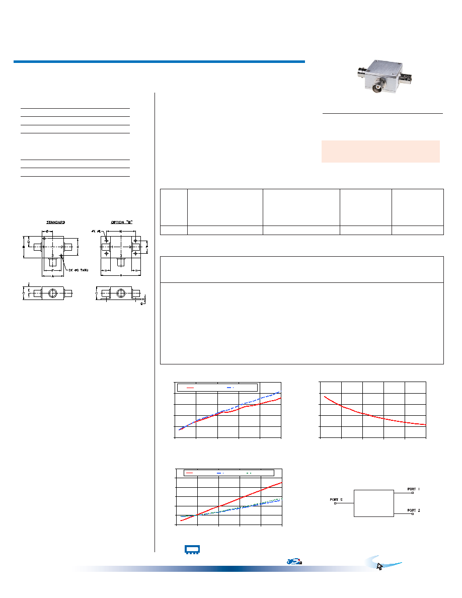
ZFSC-2-1+
2 Way-0°
50
5 to 500 MHz
Power Splitter/Combiner
Coaxial
Typical Performance Data
Maximum Ratings
Operating Temperature
-55°C to 100°C
Storage Temperature
-55°C to 100°C
Power Input (as a splitter)
1W max.
Internal Dissipation
0.125W max.
Outline Drawing
Outline Dimensions (
)
inch
mm
electrical schematic
REV. C
M127604
ZFSC-2-1+
HY/TD/CP
100614
Features
wideband, 5 to 500 MHz
low insertion loss, 0.3 dB typ.
excellent isolation, 28 dB typ.
excellent amplitude unbalance, 0.1 dB typ.
good VSWR, 1.2:1 typ.
rugged shielded case
Applications
VHF/UHF
instrumentation
communication systems
Coaxial Connections
SUM PORT
3
PORT 1
1
PORT 2
2
CASE STYLE: K18
Connectors Model
Price
Qty.
BNC
ZFSC-2-1+
$44.95
(1-9)
SMA
ZFSC-2-1-S+
$49.95
(1-9)
N-TYPE
ZFSC-2-1-N+
$49.95
(1-9)
BRACKET (OPTION "B")
$2.50
(1+)
ZFSC-2-1+
TOTAL LOSS
3.1
3.2
3.3
3.4
3.5
3.6
0
100
200
300
400
500
FREQUENCY (MHz)
T
O
T
A
L
LO
S
(d
B
)
S-1(dB)
S-2(dB)
ZFSC-2-1+
ISOLATION
20
25
30
35
40
45
0
100
200
300
400
500
FREQUENCY (MHz)
IS
O
LA
T
IO
N
(
dB
)
ZFSC-2-1+
VSWR
1.00
1.05
1.10
1.15
1.20
1.25
1.30
0
100
200
300
400
500
FREQUENCY (MHz)
V
S
W
R
#S-VSWR
#1-VSWR
#2-VSWR
Electrical Specifications
Frequency
(MHz)
Total Loss1
(dB)
Amplitude
Unbalance
(dB)
Isolation
(dB)
Phase
Unbalance
(deg.)
VSWR
S
VSWR
1
VSWR
2
S-1
S-2
BNC version shown
For option B with N-type connectors, dimension "C" increases to 0.94 inches.
20
3.17
0.00
38.54
0.08
1.02
1.05
35
3.18
3.19
0.00
37.55
0.05
1.03
1.04
1.05
80
3.23
0.00
35.20
0.01
1.05
140
3.27
3.28
0.01
32.86
0.01
1.07
1.06
170
3.29
3.30
0.01
31.68
0.03
1.09
1.06
200
3.31
3.32
0.01
30.89
0.05
1.10
1.07
225
3.33
3.34
0.02
30.37
0.09
1.11
1.07
250
3.33
3.35
0.02
29.60
0.08
1.12
1.08
290
3.35
3.38
0.03
28.75
0.13
1.14
1.09
330
3.38
3.41
0.03
28.01
0.17
1.15
1.09
1.10
370
3.39
3.43
0.04
27.35
0.21
1.17
1.10
1.11
410
3.41
3.46
0.05
26.80
0.25
1.19
1.11
1.12
450
3.43
3.48
0.05
26.31
0.30
1.21
1.12
1.13
475
3.44
3.50
0.06
26.09
0.32
1.22
1.13
1.14
500
3.46
3.52
0.06
25.83
0.34
1.23
1.13
1.14
+ RoHS compliant in accordance
with EU Directive (2002/95/EC)
The +Suffix has been added in order to identify RoHS
Compliance. See our web site for RoHS Compliance
methodologies and qualifications.
Permanent damage may occur if any of these limits are exceeded.
1. Total Loss = Insertion Loss + 3dB splitter loss.
相关PDF资料 |
PDF描述 |
|---|---|
| ZFSC-2-1B-S+ | 5 MHz - 500 MHz RF/MICROWAVE COMBINER, 0.8 dB INSERTION LOSS |
| ZFSC-4-1W | 10 MHz - 500 MHz RF/MICROWAVE COMBINER, 1.5 dB INSERTION LOSS |
| ZFSC-4-1W-BNC+ | 10 MHz - 500 MHz RF/MICROWAVE COMBINER, 1.5 dB INSERTION LOSS |
| ZFSC-4-1W-S+ | 10 MHz - 500 MHz RF/MICROWAVE COMBINER, 1.5 dB INSERTION LOSS |
| ZFSC-4-1WB-BNC+ | 10 MHz - 500 MHz RF/MICROWAVE COMBINER, 1.5 dB INSERTION LOSS |
相关代理商/技术参数 |
参数描述 |
|---|---|
| ZFSC-2-1W | 制造商:MINI 制造商全称:Mini-Circuits 功能描述:Power Splitter/Combiner 2 Way-0 50Ω 1 to 750 MHz |
| ZFSC-2-1W+ | 制造商:MINI 制造商全称:Mini-Circuits 功能描述:Power Splitter/Combiner 2 Way-0 50Ω 1 to 750 MHz |
| ZFSC-2-2 | 制造商:MINI C 功能描述: |
| ZFSC-2-2+ | 制造商:MINI 制造商全称:Mini-Circuits 功能描述:Power Splitter/Combiner 2 Way-0 50Ω 10 to 1000 MHz |
| ZFSC22500 | 制造商:MINI C 功能描述: 制造商:Mini-Circuits 功能描述: |
发布紧急采购,3分钟左右您将得到回复。