参数资料
| 型号: | 11LC161T-I/MNY |
| 厂商: | Microchip Technology |
| 文件页数: | 7/44页 |
| 文件大小: | 0K |
| 描述: | IC EEPROM 16K SER IND 8TDFN |
| 标准包装: | 3,300 |
| 格式 - 存储器: | EEPROMs - 串行 |
| 存储器类型: | EEPROM |
| 存储容量: | 16K (2K x 8) |
| 速度: | 100kHz |
| 接口: | UNI/O?(单线) |
| 电源电压: | 2.5 V ~ 5.5 V |
| 工作温度: | -40°C ~ 85°C |
| 封装/外壳: | 8-WFDFN 裸露焊盘 |
| 供应商设备封装: | 8-TDFN(2x3) |
| 包装: | 带卷 (TR) |
第1页第2页第3页第4页第5页第6页当前第7页第8页第9页第10页第11页第12页第13页第14页第15页第16页第17页第18页第19页第20页第21页第22页第23页第24页第25页第26页第27页第28页第29页第30页第31页第32页第33页第34页第35页第36页第37页第38页第39页第40页第41页第42页第43页第44页
�� �
�
�11AAXXX/11LCXXX�
�3.0�
�BUS� CHARACTERISTICS�
�If� a� command� is� terminated� in� any� manner� other� than� a�
�NoMAK/SAK� combination,� then� the� master� must� per-�
�3.1� Standby� Pulse�
�When� the� master� has� control� of� SCIO,� a� standby� pulse�
�can� be� generated� by� holding� SCIO� high� for� T� STBY� .� At�
�this� time,� the� 11XX� will� reset� and� return� to� Standby�
�mode.� Subsequently,� a� high-to-low� transition� on� SCIO�
�(the� first� low� pulse� of� the� header)� will� return� the� device�
�to� the� active� state.�
�Once� a� command� is� terminated� satisfactorily� (i.e.,� via�
�a� NoMAK/SAK� combination� during� the� Acknowledge�
�sequence),� performing� a� standby� pulse� is� not� required�
�to� begin� a� new� command� as� long� as� the� device� to� be�
�selected� is� the� same� device� selected� during� the� previ-�
�ous� command.� However,� a� period� of� T� SS� must� be�
�observed� after� the� end� of� the� command� and� before� the�
�beginning� of� the� start� header.� After� T� SS� ,� the� start�
�header� (including� T� HDR� low� pulse)� can� be� transmitted�
�in� order� to� begin� the� new� command.�
�form� a� standby� pulse� before� beginning� a� new� com-�
�mand,� regardless� of� which� device� is� to� be� selected.�
�Note:� After� a� POR/BOR� event� occurs,� a� low-�
�to-high� transition� on� SCIO� must� be� gen-�
�erated� before� proceeding� with� communi-�
�cation,� including� a� standby� pulse.�
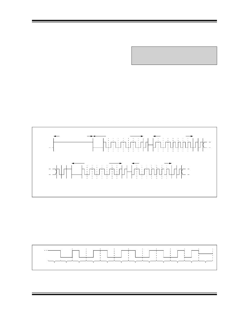
�An� example� of� two� consecutive� commands� is� shown� in�
�Figure� 3-1.� Note� that� the� device� address� is� the� same�
�for� both� commands,� indicating� that� the� same� device� is�
�being� selected� both� times.�
�A� standby� pulse� cannot� be� generated� while� the� slave�
�has� control� of� SCIO.� In� this� situation,� the� master� must�
�wait� for� the� slave� to� finish� transmitting� and� to� release�
�SCIO� before� the� pulse� can� be� generated.�
�If,� at� any� point� during� a� command,� an� error� is� detected�
�by� the� master,� a� standby� pulse� should� be� generated�
�and� the� command� should� be� performed� again.�
�FIGURE� 3-1:�
�CONSECUTIVE� COMMANDS� EXAMPLE�
�SCIO�
�Standby� Pulse� (1)�
�Start� Header�
�0� 1� 0� 1� 0� 1� 0� 1�
�Device� Address�
�1� 0� 1� 0� 0� 0� 0� 0�
�SCIO�
�Start� Header�
�0� 1� 0� 1� 0� 1� 0� 1�
�Device� Address�
�1� 0� 1� 0� 0� 0� 0� 0�
�Note� 1:� After� a� POR/BOR� event,� a� low-to-high� transition� on� SCIO� is� required� to� occur� before� the� first�
�standby� pulse.�
�3.2� Start� Data� Transfer�
�All� operations� must� be� preceded� by� a� start� header.� The�
�start� header� consists� of� holding� SCIO� low� for� a� period�
�of� T� HDR� ,� followed� by� transmitting� an� 8-bit� ‘� 01010101� ’�
�code.� This� code� is� used� to� synchronize� the� slave’s�
�internal� clock� period� with� the� master� ’s� clock� period,� so�
�accurate� timing� is� very� important.�
�When� a� standby� pulse� is� not� required� (i.e.,� between�
�successive� commands� to� the� same� device),� a� period� of�
�T� SS� must� be� observed� after� the� end� of� the� command�
�and� before� the� beginning� of� the� start� header.�
�Figure� 3-2� shows� the� waveform� for� the� start� header,�
�including� the� required� Acknowledge� sequence� at� the�
�end� of� the� byte.�
�FIGURE� 3-2:�
�SCIO�
�START� HEADER�
�T� SS�
�T� HDR�
�Data� ‘� 0� ’�
�Data� ‘� 1� ’�
�Data� ‘� 0� ’�
�Data� ‘� 1� ’�
�Data� ‘� 0� ’�
�Data� ‘� 1� ’�
�Data� ‘� 0� ’�
�Data� ‘� 1� ’�
�MAK�
�NoSAK�
�?� 2010� Microchip� Technology� Inc.�
�Preliminary�
�DS22067H-page� 7�
�相关PDF资料 |
PDF描述 |
|---|---|
| 11AA161T-I/MNY | IC EEPROM 16K SER IND 8TDFN |
| ABC49DRYI-S93 | CONN EDGECARD 98POS DIP .100 SLD |
| 166291-1 | CONN SOCKET 24-20AWG 30GOLD |
| HMC43DRYS-S734 | CONN EDGECARD 86POS DIP .100 SLD |
| 166293-1 | CONN PIN 24-20AWG CRIMP GOLD |
相关代理商/技术参数 |
参数描述 |
|---|---|
| 11LC161T-IMS | 制造商:MICROCHIP 制造商全称:Microchip Technology 功能描述:1K-16K UNI/O? Serial EEPROM Family Data Sheet |
| 11LC161T-IP | 制造商:MICROCHIP 制造商全称:Microchip Technology 功能描述:1K-16K UNI/O? Serial EEPROM Family Data Sheet |
| 11LC161T-ISN | 制造商:MICROCHIP 制造商全称:Microchip Technology 功能描述:1K-16K UNI/O? Serial EEPROM Family Data Sheet |
| 11LC161T-ITO | 制造商:MICROCHIP 制造商全称:Microchip Technology 功能描述:1K-16K UNI/O? Serial EEPROM Family Data Sheet |
| 11LC161T-ITT | 制造商:MICROCHIP 制造商全称:Microchip Technology 功能描述:1K-16K UNI/O? Serial EEPROM Family Data Sheet |
发布紧急采购,3分钟左右您将得到回复。