- 您现在的位置:买卖IC网 > PDF目录2890 > 129-0701-302 (Emerson Network Power Connectivity Johnson)CONN JACK TEST SHIELD RIGHT ANGL PDF资料下载
参数资料
| 型号: | 129-0701-302 |
| 厂商: | Emerson Network Power Connectivity Johnson |
| 文件页数: | 34/294页 |
| 文件大小: | 0K |
| 描述: | CONN JACK TEST SHIELD RIGHT ANGL |
| 产品目录绘图: | 129-0701-30(1,2) |
| 标准包装: | 5 |
| 类型: | 尖头插孔 |
| 类型: | 母头 |
| 插头/配接插头直径: | 标准 |
| 安装类型: | 通孔,水平 |
| 端子: | 焊接 |
| 绝缘体: | 非绝缘 |
| 包装: | 散装 |
| 触点表面涂层: | 金 |
| 触点材料: | 铜铍 |
| 主体材料: | TFE 碳氟化物 |
| 工作温度: | -65°C ~ 85°C |
| 产品目录页面: | 419 (CN2011-ZH PDF) |
| 其它名称: | 1290701302 J571 |
第1页第2页第3页第4页第5页第6页第7页第8页第9页第10页第11页第12页第13页第14页第15页第16页第17页第18页第19页第20页第21页第22页第23页第24页第25页第26页第27页第28页第29页第30页第31页第32页第33页当前第34页第35页第36页第37页第38页第39页第40页第41页第42页第43页第44页第45页第46页第47页第48页第49页第50页第51页第52页第53页第54页第55页第56页第57页第58页第59页第60页第61页第62页第63页第64页第65页第66页第67页第68页第69页第70页第71页第72页第73页第74页第75页第76页第77页第78页第79页第80页第81页第82页第83页第84页第85页第86页第87页第88页第89页第90页第91页第92页第93页第94页第95页第96页第97页第98页第99页第100页第101页第102页第103页第104页第105页第106页第107页第108页第109页第110页第111页第112页第113页第114页第115页第116页第117页第118页第119页第120页第121页第122页第123页第124页第125页第126页第127页第128页第129页第130页第131页第132页第133页第134页第135页第136页第137页第138页第139页第140页第141页第142页第143页第144页第145页第146页第147页第148页第149页第150页第151页第152页第153页第154页第155页第156页第157页第158页第159页第160页第161页第162页第163页第164页第165页第166页第167页第168页第169页第170页第171页第172页第173页第174页第175页第176页第177页第178页第179页第180页第181页第182页第183页第184页第185页第186页第187页第188页第189页第190页第191页第192页第193页第194页第195页第196页第197页第198页第199页第200页第201页第202页第203页第204页第205页第206页第207页第208页第209页第210页第211页第212页第213页第214页第215页第216页第217页第218页第219页第220页第221页第222页第223页第224页第225页第226页第227页第228页第229页第230页第231页第232页第233页第234页第235页第236页第237页第238页第239页第240页第241页第242页第243页第244页第245页第246页第247页第248页第249页第250页第251页第252页第253页第254页第255页第256页第257页第258页第259页第260页第261页第262页第263页第264页第265页第266页第267页第268页第269页第270页第271页第272页第273页第274页第275页第276页第277页第278页第279页第280页第281页第282页第283页第284页第285页第286页第287页第288页第289页第290页第291页第292页第293页第294页
�� �
�
�SMK� -� 50� Ohm� Connectors�
�(2.92mm)�
�INCHES� (MILLIMETERS)� ?� CUSTOMER� DRAWINGS� AVAILABLE� ON� REQUEST�
�ELECTRICAL� RATINGS�
�FIELD� REPLACEABLE� APPLICATION� NOTES�
�Impedance:� 50� ohms�
�These� field� replaceable� connectors� are� easy� to� install� and� replace.� The�
�Frequency� Range:� 0-40� GHz�
�hermetic� seal� is� mounted� into� the� circuit� module� wall� and� the� connector�
�VSWR:� (f� =� GHz)�
�can� be� removed� and� replaced� without� destroying� the� hermeticity� of� the�
�Semi-Rigid� straight� cabled� connectors� and� adapters� .............� 1.20� Max�
�Field� replaceable� (� see� typical� return� loss� graph)� ............................� N/A�
�Working� Voltage:� (VRMS� maximum)�
�Connectors� for� Cable� Type� Sea� Level� 70K� Feet�
�.086� Semi-Rigid� and� field� replaceable� .......................� 335� 85�
�.141� Semi-Rigid� and� adapters� ...................................� 500� 125�
�Dielectric� Withstanding� Voltage:� (VRMS� minimum� at� sea� level)�
�.086� Semi-Rigid� and� field� replaceable� ...........................................� 1000�
�.141� Semi-Rigid� and� adapters� .......................................................� 1500�
�circuit� housing.�
�The� field� replaceable� connector� creates� a� transition� from� microstrip�
�circuitry� to� a� coaxial� transmission� line.� The� SMK� (2.92mm)� seal� pin�
�diameter� is� .012� (.030)� to� minimize� the� capacitive� effects� on� the� circuit�
�trace.� For� optimum� electrical� performance,� the� transition� from� the�
�hermetic� seal� to� the� microstrip� trace� must� be� properly� compensated�
�which� involves� adjusting� the� microstrip� trace� width� to� minimize� any�
�impedance� discontinuities� found� in� the� transition� area.�
�Corona� Level:� (Volts� minimum� at� 70,000� feet)�
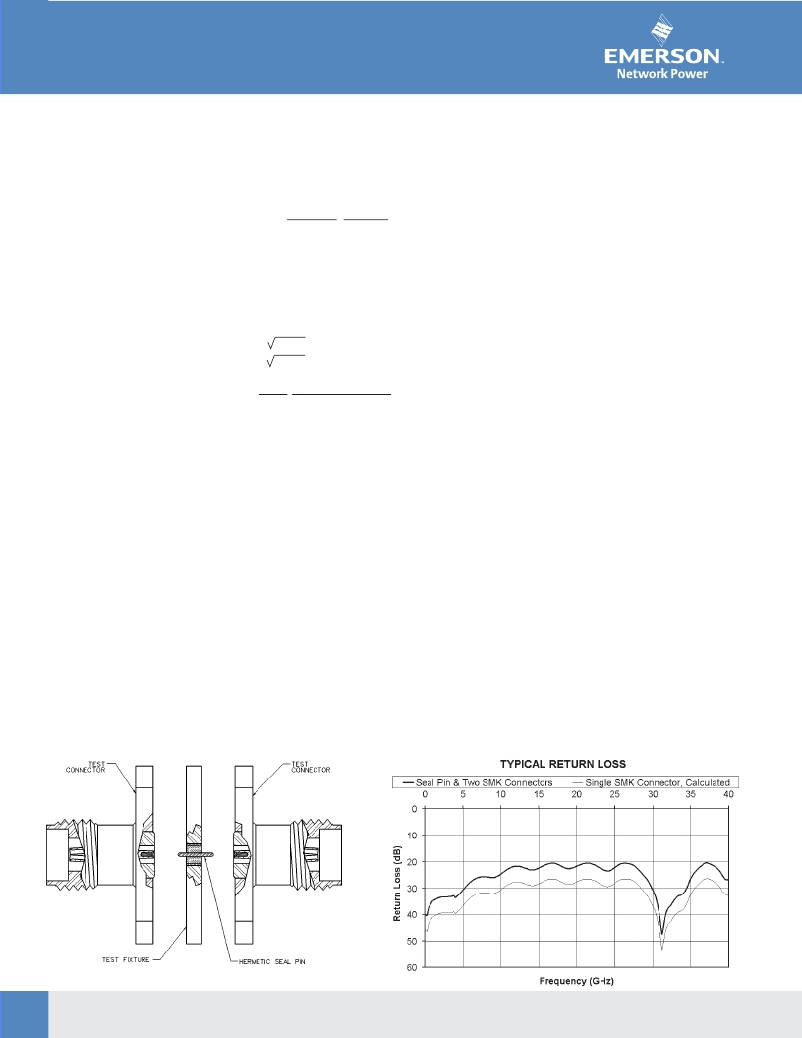
�The� plot� shown� below� is� representative� of� the� typical� return� loss� of� a�
�.086� Semi-Rigid� and� field� replaceable� .............................................� 250�
�.141� Semi-Rigid� and� adapters� .........................................................� 375�
�Johnson� field� replaceable� SMK� connector.� To� produce� the� data� shown�
�below,� a� test� fixture� is� created� using� the� Johnson� SMK� hermetic� seal.�
�Insertion� Loss:� (dB� maximum)�
�The� fixture� consists� of� a� suitably� thick� spacer� plate� with� the� hermetic�
�Adapters� ................................................� 0.06� f� (GHz),� tested� at� 6� GHz�
�seal� mounted� flush� to� both� surfaces.� Two� connectors� are� mounted� back�
�Straight� Semi-Rigid� cable� connectors� .....� 0.03� f� (GHz),� tested� at� 10� GHz�
�Insulation� Resistance:� 5000� megohms� minimum�
�Contact� Resistance:� (milliohms� maximum)� Initial After Environmental�
�Center� contact� straight� cabled� connectors� ...� 3.0*� 4.0�
�Center� contact� adapters� ................................� 4.0� 6.0�
�Field� replaceable� connectors� .........................� 6.0� 8.0�
�to� back� around� the� fixture� and� the� VSWR� of� this� test� assembly� is�
�measured.� The� calculated� return� loss� trace� shown� is� equivalent� to� the�
�square� root� of� the� measured� VSWR� of� the� test� assembly.� Since� the�
�connectors� tested� are� of� identical� design,� it� can� be� stated� with� fair�
�accuracy� that� the� calculated� data� shown� represents� the� response� of� a�
�single� field� replaceable� connector� and� its� transition� to� the� hermetic� seal.�
�Outer� contact� (all� connectors)� .......................� 2.0� N/A�
�Body� to� cable� (gold� plated� connectors)� .........� 0.5� N/A�
�Body� to� cable� (passivated� connectors)� ..........� 5.0� N/A�
�RF� Leakage:� (dB� minimum,� tested� at� 2.5� GHz)� .............................� -90dB�
�RF� High� Potential� Withstanding� Voltage:�
�(VRMS� minimum,� tested� at� 4� and� 7� MHz)� =�
�.086� Semi-Rigid� and� field� replaceable� ............................................� 670�
�.141� Semi-Rigid� and� adapters� ......................................................� 1000�
�Although� we� do� not� publish� a� VSWR� specification� for� field� replaceable�
�connectors,� typical� connector� return� loss� can� be� expected� to� be� better�
�than� 20� dB� through� 40� GHz.� A� VSWR� specification� is� not� stated� because�
�an� industry� standard� method� for� testing� field� replaceable� connectors�
�does� not� exist.� The� actual� performance� of� the� connector� is� dependent�
�upon� the� following:�
�1.� For� optimum� electrical� performance,� we� recommend� the� use� of� our�
�standard� 142-1000-033� hermetic� seal� with� a� pin� diameter� of� .0120�
�ENVIRONMENTAL� RATINGS�
�(0.305)� +/-� .0005� (0.013).�
�(Meets� or� exceeds� the� applicable� paragraph� of� MIL-C-39012)�
�2.� It� is� recommended� that� the� hermetic� seal� be� mounted� flush� with� the�
�Temperature� Range:� -� 65� °� C� to� +� 165� °� C�
�circuit� housing.� Tolerance� variations� between� the� hermetic� seal� and�
�Thermal� Shock:� MIL-STD-202,� Method� 107,� Condition� B�
�machined� housing� do� not� always� guarantee� an� optimum� transition� to�
�Corrosion:� MIL-STD-202,� Method� 101,� Condition� B�
�the� connector.� Some� manufacturers� recommend� an� additional�
�Shock:� MIL-STD-202,� Method� 213,� Condition� I�
�counterbore� in� the� circuit� housing� to� accommodate� a� solder� washer�
�Vibration:� MIL-STD-202,� Method� 204,� Condition� D�
�during� installation� of� the� seal.� We� do� not� recommend� this� type� of�
�Moisture� Resistance:� MIL-STD-202,� Method� 106�
�installation� because,� if� the� counterbore� is� not� completely� filled� with�
�solder,� electrical� discontinuities� may� be� created.�
�3.� The� transition� between� the� hermetic� seal� pin� and� the� microstrip� trace�
�will� effect� electrical� performance,� as� stated� above.� Several� different�
�methods� of� hermetic� seal� mounting� and� seal� pin� to� microstrip� trace�
�FIELD� REPLACEABLE� TEST� ASSEMBLY�
�attachment� are� used� in� the� industry.�
�34�
�Connectivity� Solutions�
�Tel:� 800-247-8256� ?� Fax:� 507-833-6287� ?� www.EmersonNetworkPower.com/connectivity�
�相关PDF资料 |
PDF描述 |
|---|---|
| RNCF0805DTC11K3 | RES 11.3K OHM 1/10W 0.5% 0805 |
| RNCF0805DTC11R0 | RES 11 OHM 1/10W 0.5% 0805 |
| RNCF0805DTC100K | RES 100K OHM 1/10W 0.5% 0805 |
| RNCF0805DTC100R | RES 100 OHM 1/10W 0.5% 0805 |
| RNCF0805DTC10R0 | RES 10 OHM 1/10W 0.5% 0805 |
相关代理商/技术参数 |
参数描述 |
|---|---|
| 129071 | 制造商:Brady Corporation 功能描述:B302 10X14 BLK/YEL CAUTION SLIPPERY TRIP |
| 1290710000 | 制造商:Weidmuller 功能描述:S2C-SMT 3.50/22/180LF 1.5SN BK |
| 1290720000 | 制造商:Weidmuller 功能描述:S2C-SMT 3.50/24/180LF 1.5SN BK |
| 1290730000 | 制造商:Weidmuller 功能描述:S2C-SMT 3.50/26/180LF 1.5SN BK |
| 1290740000 | 制造商:Weidmuller 功能描述:S2C-SMT 3.50/28/180LF 1.5SN BK |
发布紧急采购,3分钟左右您将得到回复。