- 您现在的位置:买卖IC网 > PDF目录2890 > 129-0701-302 (Emerson Network Power Connectivity Johnson)CONN JACK TEST SHIELD RIGHT ANGL PDF资料下载
参数资料
| 型号: | 129-0701-302 |
| 厂商: | Emerson Network Power Connectivity Johnson |
| 文件页数: | 52/294页 |
| 文件大小: | 0K |
| 描述: | CONN JACK TEST SHIELD RIGHT ANGL |
| 产品目录绘图: | 129-0701-30(1,2) |
| 标准包装: | 5 |
| 类型: | 尖头插孔 |
| 类型: | 母头 |
| 插头/配接插头直径: | 标准 |
| 安装类型: | 通孔,水平 |
| 端子: | 焊接 |
| 绝缘体: | 非绝缘 |
| 包装: | 散装 |
| 触点表面涂层: | 金 |
| 触点材料: | 铜铍 |
| 主体材料: | TFE 碳氟化物 |
| 工作温度: | -65°C ~ 85°C |
| 产品目录页面: | 419 (CN2011-ZH PDF) |
| 其它名称: | 1290701302 J571 |
第1页第2页第3页第4页第5页第6页第7页第8页第9页第10页第11页第12页第13页第14页第15页第16页第17页第18页第19页第20页第21页第22页第23页第24页第25页第26页第27页第28页第29页第30页第31页第32页第33页第34页第35页第36页第37页第38页第39页第40页第41页第42页第43页第44页第45页第46页第47页第48页第49页第50页第51页当前第52页第53页第54页第55页第56页第57页第58页第59页第60页第61页第62页第63页第64页第65页第66页第67页第68页第69页第70页第71页第72页第73页第74页第75页第76页第77页第78页第79页第80页第81页第82页第83页第84页第85页第86页第87页第88页第89页第90页第91页第92页第93页第94页第95页第96页第97页第98页第99页第100页第101页第102页第103页第104页第105页第106页第107页第108页第109页第110页第111页第112页第113页第114页第115页第116页第117页第118页第119页第120页第121页第122页第123页第124页第125页第126页第127页第128页第129页第130页第131页第132页第133页第134页第135页第136页第137页第138页第139页第140页第141页第142页第143页第144页第145页第146页第147页第148页第149页第150页第151页第152页第153页第154页第155页第156页第157页第158页第159页第160页第161页第162页第163页第164页第165页第166页第167页第168页第169页第170页第171页第172页第173页第174页第175页第176页第177页第178页第179页第180页第181页第182页第183页第184页第185页第186页第187页第188页第189页第190页第191页第192页第193页第194页第195页第196页第197页第198页第199页第200页第201页第202页第203页第204页第205页第206页第207页第208页第209页第210页第211页第212页第213页第214页第215页第216页第217页第218页第219页第220页第221页第222页第223页第224页第225页第226页第227页第228页第229页第230页第231页第232页第233页第234页第235页第236页第237页第238页第239页第240页第241页第242页第243页第244页第245页第246页第247页第248页第249页第250页第251页第252页第253页第254页第255页第256页第257页第258页第259页第260页第261页第262页第263页第264页第265页第266页第267页第268页第269页第270页第271页第272页第273页第274页第275页第276页第277页第278页第279页第280页第281页第282页第283页第284页第285页第286页第287页第288页第289页第290页第291页第292页第293页第294页
�� �
�
�SMA� -� 50� Ohm� Connectors�
�End� Launch� Connectors� -� A� Johnson� Original�
�INCHES� (MILLIMETERS)� ?� CUSTOMER� DRAWINGS� AVAILABLE� ON� REQUEST�
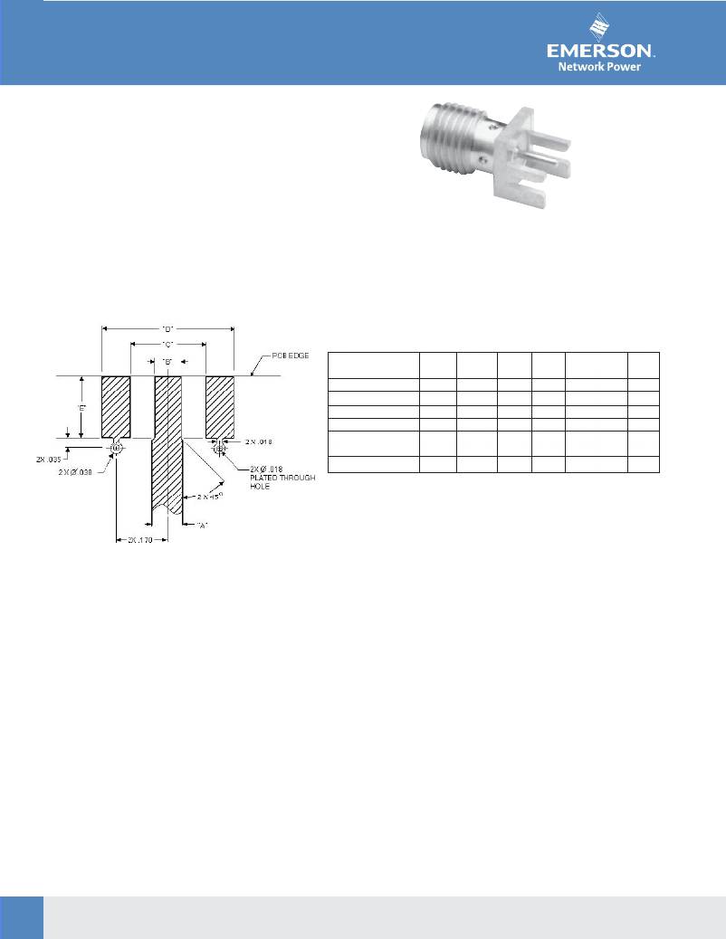
�The� End� Launch� connector� is� attached� to� the� circuit� board�
�by� inserting� the� board� edge� between� the� legs� and� solder-�
�ing� the� legs� and� center� conductor� to� pads� on� the� board.�
�For� optimum� high� frequency� performance,� the� connector�
�to� circuit� board� transition� must� be� adjusted� for� low� VSWR.�
�To� compensate� for� the� transition� from� coax� to� microstrip,�
�trace� widths� “A”� and� “B”� must� be� adjusted� based� on� circuit�
�board� thickness.� When� properly� adjusted,� this� technique�
�yields� a� low� VSWR� over� a� wide� bandwidth.�
�both� sides.� The� copper� was� left� on� the� bottom� of� the� board�
�to� create� a� ground� plane� for� the� 50� Ohm� microstrip� structure.�
�The� tabulated� dimensions� “A”,� “B”,� “C”,� "D",� and� “E”� were�
�While� not� all� inclusive,� these� dimensions� are� given� as�
�determined� experimentally� to� achieve� low� VSWR� (typically�
�reference� information� for� selected� SMA� End� Launch�
�less� than� 1.5� up� to� 18� GHz).� The� circuit� board� used� for�
�connectors.� Further� adjustments� may� be� necessary�
�these� tests� was� double-sided� FR� 4� with� 1� oz.� copper� on�
�depending� upon� the� application.� All� dimensions� are� in� inches.�
�PART� BASE� BOARD�
�NO.� WIDTH� THICK�
�142-0701-801/806� .375� .062�
�142-0701-851/861� .375� .062�
�142-0701-871/876� .375� .062�
�142-0711-821/826� .250� .062�
�142-0711-871/876� .375� .047�
�142-0711-881/886� .375� .047�
�142-0701-881/886� .375� .031�
�“A”�
�.103�
�.103�
�.103�
�.103�
�.083�
�.083�
�.050�
�“B”�
�.090�
�.090�
�.090�
�.070�
�.075�
�.075�
�.045�
�“C”�
�.250�
�.250�
�.250�
�.170�
�.250�
�.250�
�.250�
�“D”�
�.440�
�.440�
�.440�
�.380�
�.440�
�.440�
�.440�
�“E”�
�.200�
�.200�
�.200�
�.165�
�.200�
�.200�
�.200�
�Tabulated� Dimensions� “A”,� “B”,� “C”� and� “D”� are� symmetrical� about� the� center� line�
�Surface� Mount� Versions� Available!�
�SMA� End� Launch� Specifications�
�ELECTRICAL� RATINGS�
�Impedance:� 50� Ohms�
�Frequency� Range:� 0-18� GHz�
�VSWR:� Dependent� upon� application�
�Working� Voltage� (VRMS� max.):� 335� @� Sea� Level,� 85� @� 70K� Feet�
�Dielectric� Withstanding� Voltage� (VRMS� min.� at� sea� level):� 1000�
�Corona� Level� (Volts� min.� at� 70,000� feet):� 250�
�Insulation� Resistance:� 5000� megohms� min�
�Contact� Resistance� (milliohms� max.):� 3.0� Initial,� 4.0� after� environmental�
�ENVIRONMENTAL� RATINGS�
�(Meets� or� exceeds� the� applicable� paragraph� of� MIL-C-39012)�
�Temperature� Range:� -65� o� to� +� 165� o� C�
�Thermal� Shock:� MIL-STD-202,� Method� 107,� Condition� B�
�Corrosion:� MIL-STD-202,� Method� 101,� Condition� B�
�Shock:� MIL-STD-303,� Method� 213,� Condition� I�
�Vibration:� MIL-STD-202,� Method� 204,� Condition� D�
�Moisture� Resistance:� MIL-STD-202,� Method� 106�
�RF� High� Potential� Withstanding� Voltage� (VRMS� min.� tested� at�
�4� and� 7� MHz):� 670�
�MATERIAL� SPECIFICATIONS�
�Bodies:� Brass� per� QQ-B-626,� gold� plated*� per�
�MECHANICAL� RATINGS�
�Engagement� Design:� MIL-C-39012,� Series� SMA�
�Engagement/Disengagement� Force:� 2� inch-pounds� max.�
�Mating� Torque:� 7� to� 10� inch-pounds�
�Coupling� Proof� Torque:� 15� inch-pounds� min.�
�Coupling� Nut� Retention:� 60� pounds� min.�
�Contact� Retention� Force:� 6� lbs� min.� axial� force,� 4� inch-ounce� min.� torque�
�Durability:� 500� cycles� min.�
�MIL-G-45204� .00001"� min.� or� nickel� plated� per� QQ-N-290�
�Contacts:�
�Male� -� brass� per� QQ-B-626,� gold� plated� per� MIL-G-45204� .00003"� min.�
�Female� -� beryllium� copper� per� QQ-C-530,� gold� plated�
�per� MIL-G-45204� .00003"� min.�
�Nut� Retention� Spring:� Beryllium� copper� per� QQ-C-533.� Unplated�
�Insulators:� PTFE� fluorocarbon� per� ASTM� D� 1710� and� ASTM� D� 1457�
�Mounting� Hardware:� Brass� per� QQ-B-626� or� QQ-B-613,� gold� plated� per�
�MIL-G-45204� .00001"� min.� or� nickel� plated� per� QQ-N-290�
�*All� gold� plated� parts� include� a�
�.00005"� min.� nickel� underplate� barrier� layer.�
�52�
�Connectivity� Solutions�
�Tel:� 800-247-8256� ?� Fax:� 507-833-6287� ?� www.EmersonNetworkPower.com/connectivity�
�相关PDF资料 |
PDF描述 |
|---|---|
| RNCF0805DTC11K3 | RES 11.3K OHM 1/10W 0.5% 0805 |
| RNCF0805DTC11R0 | RES 11 OHM 1/10W 0.5% 0805 |
| RNCF0805DTC100K | RES 100K OHM 1/10W 0.5% 0805 |
| RNCF0805DTC100R | RES 100 OHM 1/10W 0.5% 0805 |
| RNCF0805DTC10R0 | RES 10 OHM 1/10W 0.5% 0805 |
相关代理商/技术参数 |
参数描述 |
|---|---|
| 129071 | 制造商:Brady Corporation 功能描述:B302 10X14 BLK/YEL CAUTION SLIPPERY TRIP |
| 1290710000 | 制造商:Weidmuller 功能描述:S2C-SMT 3.50/22/180LF 1.5SN BK |
| 1290720000 | 制造商:Weidmuller 功能描述:S2C-SMT 3.50/24/180LF 1.5SN BK |
| 1290730000 | 制造商:Weidmuller 功能描述:S2C-SMT 3.50/26/180LF 1.5SN BK |
| 1290740000 | 制造商:Weidmuller 功能描述:S2C-SMT 3.50/28/180LF 1.5SN BK |
发布紧急采购,3分钟左右您将得到回复。