- 您现在的位置:买卖IC网 > PDF目录4255 > 25AA320XT-I/ST (Microchip Technology)IC EEPROM 32KBIT 1MHZ 8TSSOP PDF资料下载
参数资料
| 型号: | 25AA320XT-I/ST |
| 厂商: | Microchip Technology |
| 文件页数: | 7/26页 |
| 文件大小: | 0K |
| 描述: | IC EEPROM 32KBIT 1MHZ 8TSSOP |
| 标准包装: | 2,500 |
| 格式 - 存储器: | EEPROMs - 串行 |
| 存储器类型: | EEPROM |
| 存储容量: | 32K (4K x 8) |
| 速度: | 1MHz |
| 接口: | SPI 3 线串行 |
| 电源电压: | 1.8 V ~ 5.5 V |
| 工作温度: | -40°C ~ 85°C |
| 封装/外壳: | 8-TSSOP(0.173",4.40mm 宽) |
| 供应商设备封装: | 8-TSSOP |
| 包装: | 带卷 (TR) |
| 其它名称: | 25AA320XTI/ST |
�� �
�
�25AA320/25LC320/25C320�
�3.0�
�FUNCTIONAL� DESCRIPTION�
�3.3�
�Write� Sequence�
�3.1�
�Principles� Of� Operation�
�Prior� to� any� attempt� to� write� data� to� the� 25XX320,� the�
�write� enable� latch� must� be� set� by� issuing� the� WREN�
�The� 25XX320� are� 4096� byte� Serial� EEPROMs�
�designed� to� interface� directly� with� the� Serial� Peripheral�
�Interface� (SPI)� port� of� many� of� today’s� popular�
�microcontroller� families,� including� Microchip’s�
�PIC16C6X/7X� microcontrollers.� It� may� also� interface�
�with� microcontrollers� that� do� not� have� a� built-in� SPI� port�
�by� using� discrete� I/O� lines� programmed� properly� with�
�the� software.�
�The� 25XX320� contains� an� 8-bit� instruction� register.� The�
�device� is� accessed� via� the� SI� pin,� with� data� being�
�clocked� in� on� the� rising� edge� of� SCK.� The� CS� pin� must�
�be� low� and� the� HOLD� pin� must� be� high� for� the� entire�
�operation.�
�Table� 3-1� contains� a� list� of� the� possible� instruction�
�bytes� and� format� for� device� operation.� All� instructions,�
�addresses� and� data� are� transferred� MSB� first,� LSB� last.�
�Data� is� sampled� on� the� first� rising� edge� of� SCK� after� CS�
�goes� low.� If� the� clock� line� is� shared� with� other�
�peripheral� devices� on� the� SPI� bus,� the� user� can� assert�
�the� HOLD� input� and� place� the� 25XX320� in� ‘HOLD’�
�mode.� After� releasing� the� HOLD� pin,� operation� will�
�resume� from� the� point� when� the� HOLD� was� asserted.�
�instruction� (Figure� 3-4).� This� is� done� by� setting� CS� low�
�and� then� clocking� out� the� proper� instruction� into� the�
�25XX320.� After� all� eight� bits� of� the� instruction� are�
�transmitted,� the� CS� must� be� brought� high� to� set� the�
�write� enable� latch.� If� the� write� operation� is� initiated�
�immediately� after� the� WREN� instruction� without� CS�
�being� brought� high,� the� data� will� not� be� written� to� the�
�array� because� the� write� enable� latch� will� not� have� been�
�properly� set.�
�Once� the� write� enable� latch� is� set,� the� user� may�
�proceed� by� setting� the� CS� low,� issuing� a� WRITE�
�instruction,� followed� by� the� 16-bit� address,� with� the� four�
�MSBs� of� the� address� being� “don’t� care”� bits,� and� then�
�the� data� to� be� written.� Up� to� 32� bytes� of� data� can� be�
�sent� to� the� 25XX320� before� a� write� cycle� is� necessary.�
�The� only� restriction� is� that� all� of� the� bytes� must� reside�
�in� the� same� page.� A� page� address� begins� with� xxxx�
�xxxx� xxx0� 0000� and� ends� with� xxxx� xxxx� xxx1�
�1111� .� If� the� internal� address� counter� reaches� xxxx�
�xxxx� xxx1� 1111� and� the� clock� continues,� the� counter�
�will� roll� back� to� the� first� address� of� the� page� and� over-�
�write� any� data� in� the� page� that� may� have� been� written.�
�For� the� data� to� be� actually� written� to� the� array,� the� CS�
�3.2�
�Read� Sequence�
�must� be� brought� high� after� the� Least� Significant� bit� (D0)�
�of� the� n� th� data� byte� has� been� clocked� in.� If� CS� is�
�The� device� is� selected� by� pulling� CS� low.� The� 8-bit�
�READ� instruction� is� transmitted� to� the� 25XX320� fol-�
�lowed� by� the� 16-bit� address,� with� the� four� MSBs� of� the�
�address� being� “don’t� care”� bits.� After� the� correct� READ�
�instruction� and� address� are� sent,� the� data� stored� in� the�
�memory� at� the� selected� address� is� shifted� out� on� the�
�SO� pin.� The� data� stored� in� the� memory� at� the� next�
�address� can� be� read� sequentially� by� continuing� to� pro-�
�vide� clock� pulses.� The� internal� Address� Pointer� is� auto-�
�matically� incremented� to� the� next� higher� address� after�
�each� byte� of� data� is� shifted� out.� When� the� highest�
�address� is� reached� (0FFFh),� the� address� counter� rolls�
�over� to� address� 0000h� allowing� the� read� cycle� to� be�
�continued� indefinitely.� The� read� operation� is� terminated�
�by� raising� the� CS� pin� (Figure� 3-1).�
�brought� high� at� any� other� time,� the� write� operation� will�
�not� be� completed.� Refer� to� Figure� 3-2� and� Figure� 3-3�
�for� more� detailed� illustrations� on� the� byte� write�
�sequence� and� the� page� write� sequence,� respectively.�
�While� the� write� is� in� progress,� the� STATUS� register� may�
�be� read� to� check� the� status� of� the� WPEN,� WIP,� WEL,�
�BP1� and� BP0� bits� (Figure� 3-6).� A� read� attempt� of� a�
�memory� array� location� will� not� be� possible� during� a�
�write� cycle.� When� the� write� cycle� is� completed,� the�
�write� enable� latch� is� reset.�
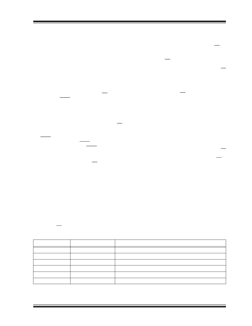
�TABLE� 3-1:�
�INSTRUCTION� SET�
�Instruction� Name�
�READ�
�WRITE�
�WRDI�
�WREN�
�RDSR�
�WRSR�
�Instruction� Format�
�0000� 0011�
�0000� 0010�
�0000� 0100�
�0000� 0110�
�0000� 0101�
�0000� 0001�
�Description�
�Read� data� from� memory� array� beginning� at� selected� address�
�Write� data� to� memory� array� beginning� at� selected� address�
�Reset� the� write� enable� latch� (disable� write� operations)�
�Set� the� write� enable� latch� (enable� write� operations)�
�Read� STATUS� register�
�Write� STATUS� register�
�?� 2008� Microchip� Technology� Inc.�
�DS21227F-page� 7�
�相关PDF资料 |
PDF描述 |
|---|---|
| 25LC320X-I/ST | IC EEPROM 32KBIT 2MHZ 8TSSOP |
| 25LC320AT-E/MNY | IC EEPROM 32KBIT 10MHZ 8TDFN |
| 25LC320AX-E/ST | IC EEPROM 32KBIT 10MHZ 8TSSOP |
| 3-1393561-6 | HARDWARE CONTACT TUBE 15-37 POS |
| 3-1393561-5 | HARDWARE CONTACT TUBE 9-37 POS |
相关代理商/技术参数 |
参数描述 |
|---|---|
| 25AA512 | 制造商:MICROCHIP 制造商全称:Microchip Technology 功能描述:512 Kbit SPI Bus Serial EEPROM |
| 25AA512_10 | 制造商:MICROCHIP 制造商全称:Microchip Technology 功能描述:512 Kbit SPI Bus Serial EEPROM |
| 25AA512-1/MF | 制造商:MICROCHIP 制造商全称:Microchip Technology 功能描述:512 Kbit SPI Bus Serial EEPROM |
| 25AA512-1/P | 制造商:MICROCHIP 制造商全称:Microchip Technology 功能描述:512 Kbit SPI Bus Serial EEPROM |
| 25AA512-1/SN | 制造商:MICROCHIP 制造商全称:Microchip Technology 功能描述:512 Kbit SPI Bus Serial EEPROM |
发布紧急采购,3分钟左右您将得到回复。