- 您现在的位置:买卖IC网 > PDF目录33211 > 2MBI150NC-120 150 A, 1200 V, N-CHANNEL IGBT PDF资料下载
参数资料
| 型号: | 2MBI150NC-120 |
| 元件分类: | IGBT 晶体管 |
| 英文描述: | 150 A, 1200 V, N-CHANNEL IGBT |
| 封装: | M233, 7 PIN |
| 文件页数: | 1/4页 |
| 文件大小: | 99K |
| 代理商: | 2MBI150NC-120 |
IGBT MODULE ( N series )
n
n Features
Square RBSOA
Low Saturation Voltage
Less Total Power Dissipation
Improved FWD Characteristic
Minimized Internal Stray Inductance
Overcurrent Limiting Function (
4~5 Times Rated Current)
n
n Applications
High Power Switching
A.C. Motor Controls
D.C. Motor Controls
Uninterruptible Power Supply
n
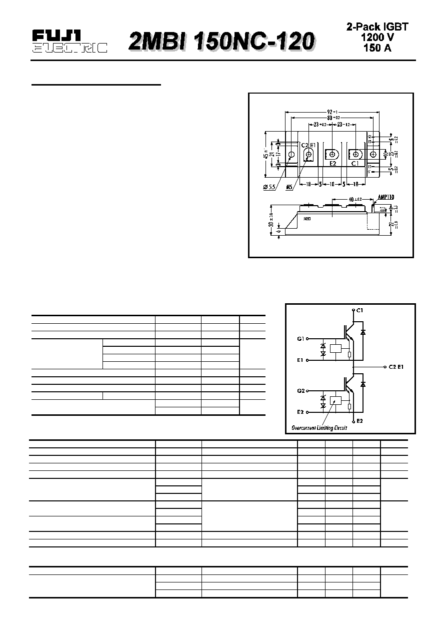
n Outline Drawing
n
n Maximum Ratings and Characteristics
Absolute Maximum Ratings ( T
c=25°C
)
Items
Symbols
Ratings
Units
Collector-Emitter Voltage
VCES
1200
V
Gate -Emitter Voltage
VGES
± 20
V
Continuous
IC
150
Collector
1ms
IC PULSE
300
Current
Continuous
-IC
150
1ms
-IC PULSE
300
Max. Power Dissipation
PC
1100
W
Operating Temperature
Tj
+150
°C
Storage Temperature
Tstg
-40
+125
°C
Isolation Voltage
A.C. 1min.
Vis
2500
V
Mounting *1
3.5
Terminals *1
3.5
Note: *1:Recommendable Value; 2.5
3.5 Nm (M5)
Electrical Characteristics ( at T
j=25°C )
Items
Symbols
Test Conditions
Min.
Typ.
Max.
Units
Zero Gate Voltage Collector Current
ICES
VGE=0V VCE=1200V
2.0
mA
Gate-Emitter Leackage Current
IGES
VCE=0V VGE=
± 20V
30
A
Gate-Emitter Threshold Voltage
VGE(th)
VGE=20V IC=150mA
4.5
7.5
V
Collector-Emitter Saturation Voltage
VCE(sat)
VGE=15V IC=150A
3.3
V
Input capacitance
Cies
VGE=0V
24000
Output capacitance
Coes
VCE=10V
8700
pF
Reverse Transfer capacitance
Cres
f=1MHz
7740
tON
VCC=600V
0.65
1.2
tr
IC=150A
0.25
0.6
tOFF
VGE=
± 15V
0.85
1.5
tf
RG=5.6
0.35
0.5
Diode Forward On-Voltage
VF
IF=150A VGE=0V
3.0
V
Reverse Recovery Time
trr
IF=150A
350
ns
Thermal Characteristics
Items
Symbols
Test Conditions
Min.
Typ.
Max.
Units
Rth(j-c)
IGBT
0.11
Thermal Resistance
Rth(j-c)
Diode
0.33
°C/W
Rth(c-f)
With Thermal Compound
0.025
n
n Equivalent Circuit
Screw Torque
Turn-on Time
Turn-off Time
s
A
Nm
相关PDF资料 |
PDF描述 |
|---|---|
| 2MBI200F-060 | 200 A, 600 V, N-CHANNEL IGBT |
| 2MBI200PB-140 | 300 A, 1400 V, N-CHANNEL IGBT |
| 2MBI200S-120 | 300 A, 1200 V, N-CHANNEL IGBT |
| 2MBI225VJ-120-50 | 225 A, 1200 V, N-CHANNEL IGBT |
| 2MBI25F-120 | 25 A, 1200 V, N-CHANNEL IGBT |
相关代理商/技术参数 |
参数描述 |
|---|---|
| 2MBI150NE-120 | 制造商:FUJI 制造商全称:Fuji Electric 功能描述:IGBT MODULE ( N series ) |
| 2MBI150NT-120 | 制造商:FUJI 制造商全称:Fuji Electric 功能描述:IGBT module |
| 2MBI150NT-120-01 | 制造商:FUJI 制造商全称:Fuji Electric 功能描述:IGBT module |
| 2MBI150NT-120A | 制造商:FUJI 制造商全称:Fuji Electric 功能描述:IGBT module |
| 2MBI150P-140 | 制造商:FUJI 制造商全称:Fuji Electric 功能描述:IGBT MODULE ( P-Series ) |
发布紧急采购,3分钟左右您将得到回复。