- 您现在的位置:买卖IC网 > PDF目录293971 > 5962-8981702ZX (CYPRESS SEMICONDUCTOR CORP) 32K X 8 UVPROM, 45 ns, CQCC32 PDF资料下载
参数资料
| 型号: | 5962-8981702ZX |
| 厂商: | CYPRESS SEMICONDUCTOR CORP |
| 元件分类: | PROM |
| 英文描述: | 32K X 8 UVPROM, 45 ns, CQCC32 |
| 封装: | CERAMIC, LCC-32 |
| 文件页数: | 4/11页 |
| 文件大小: | 245K |
| 代理商: | 5962-8981702ZX |
CY7C271
CY7C274
Document #: 38-04008 Rev. *B
Page 2 of 11
Maximum Ratings[1]
(Above which the useful life may be impaired. For user guide-
lines, not tested.)
Storage Temperature
..................................... 65°C to +150°C
Ambient Temperature with
Power Applied
..................................................55°C to +125°C
Supply Voltage to Ground Potential
.................0.5V to +7.0V
DC Voltage Applied to Outputs
in High Z State
.....................................................0.5V to +7.0V
DC Input Voltage
.................................................3.0V to +7.0V
DC Program Voltage .................................................... 13.0V
Static Discharge Voltage............................................ >2001V
(per MIL-STD-883, Method 3015)
Latch-Up Current ..................................................... >200 mA
UV Exposure ................................................ 7258 Wsec/cm2
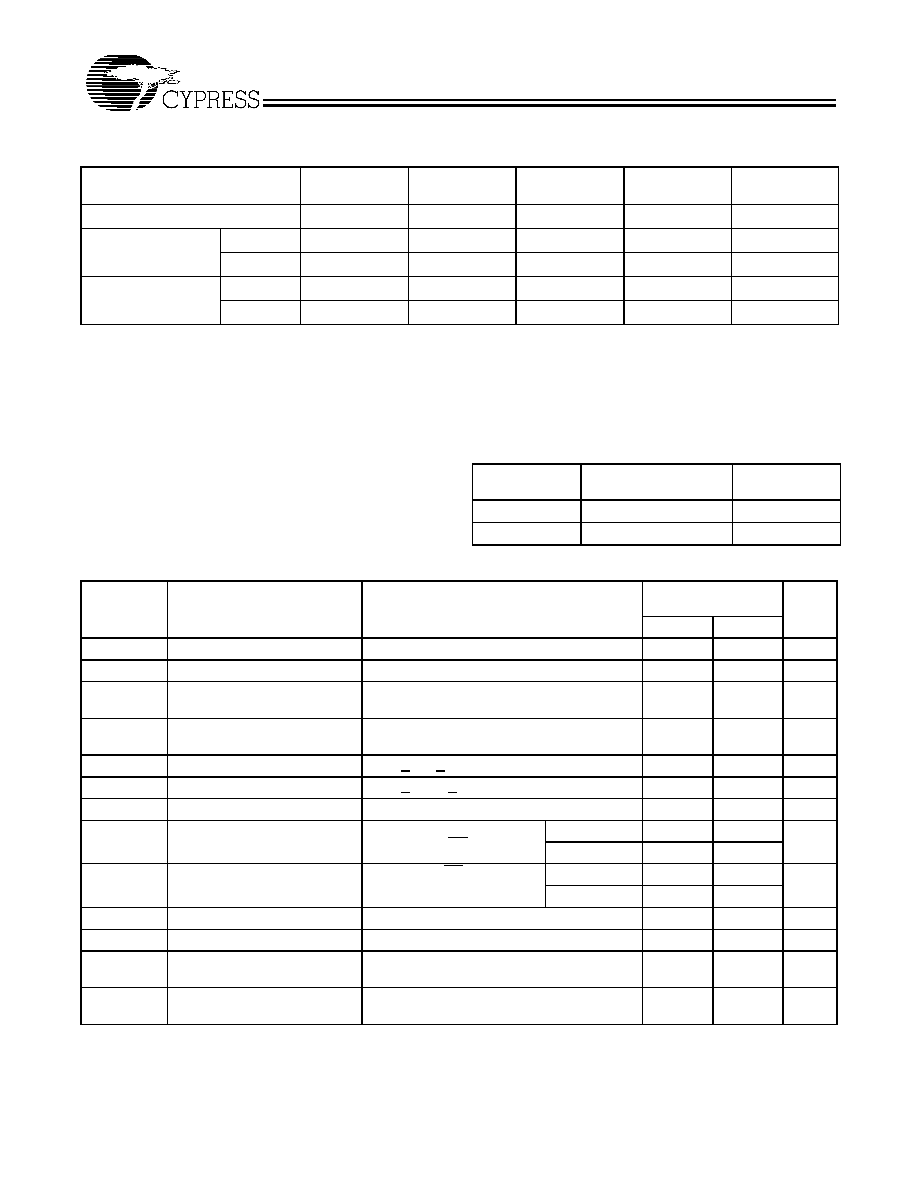
Selection Guide
7C274-30
7C271-35
7C274-35
7C271-45
7C274-45
7C271-55
Unit
Maximum Access Time
30
35
45
55
ns
Maximum Operating
Current
Com’l
120
mA
Military
130
mA
Standby Current
Com’l
30
mA
Military
40
mA
Operating Range
Range
Ambient
Temperature
VCC
Commercial
0
°C to +70°C
5V
±10%
Military[2]
55
°C to +125°C
5V
±10%
Electrical Characteristics Over the Operating Range[3]
7C271- 35, 45, 55
7C274-30, 35, 45,
Parameter
Description
Test Conditions
Min.
Max.
Unit
VOH
Output HIGH Voltage
VCC = Min., IOH = 2.0 mA
2.4
V
VOL
Output LOW Voltage
VCC = Min., IOL = 8.0 mA
[4]
0.4
V
VIH
Input HIGH Level
Guaranteed Input Logical HIGH Voltage for All
Inputs
2.0
VCC
V
VIL
Input LOW Level
Guaranteed Input Logical LOW Voltage for All
Inputs
0.8
V
IIX
Input Current
GND < VIN < VCC
10
+10
A
IOZ
Output Leakage Current
GND < VOUT < VCC, Output Disabled
40
+40
A
IOS
Output Short Circuit Current[5]
VCC = Max., VOUT = GND
20
90
mA
ICC
Power Supply Current
VCC = Max., VIN = 2.0V,
IOUT = 0 mA, CE=VIL
Commercial
120
mA
Military
130
ISB
Standby Supply Current
VCC = Max., CE = VIH,
IOUT = 0 mA
Commercial
30
mA
Military
40
VPP
Programming Supply Voltage
12
13
V
IPP
Programming Supply Current
50
mA
VIHP
Input HIGH Programming
Voltage
3.0
V
VILP
Input LOW Programming
Voltage
0.4
V
Notes:
1.
The voltage on any input or I/O pin cannot exceed the power pin during power-up.
2.
TA is the “instant on” case temperature.
3.
See the last page of this specification for Group A subgroup testing information.
4.
6.0 mA military
5.
For test purposes, not more than one output at a time should be shorted. Short circuit test duration should not exceed 30 seconds.
相关PDF资料 |
PDF描述 |
|---|---|
| 5962-9096301MYA | 19-BIT, DSP-FFT PROCESSOR, PPGA89 |
| 5962-9176201M3A | 8-BIT, DSP-PIPELINE REGISTER, QCC28 |
| 5962-9205803MYA | 32-BIT, 40 MHz, OTHER DSP, CQFP132 |
| 5962-9205805QXA | 32-BIT, 60 MHz, OTHER DSP, CPGA141 |
| 5962-9309101HYA | EEPROM 5V MODULE, CDIP32 |
相关代理商/技术参数 |
参数描述 |
|---|---|
| 5962-8981703XA | 制造商:QP Semiconductor 功能描述:EPROM UV 256K-Bit 32K x 8 35ns 28-Pin CDIP |
| 5962-8981704ZX | 制造商:Cypress Semiconductor 功能描述:EPROM UV 256K-Bit 32K x 8 55ns 32-Pin LCC |
| 5962-8981705UA | 制造商:Cypress Semiconductor 功能描述:32K X 8 POWER SWITCHED AND REPROGRAMMABLE PROM |
| 5962-8982101PA | 制造商:e2v technologies 功能描述:Pref DRVR Dual 4.5V to 15V 1133mW 8-Pin CDIP |
| 59628982303MZC | 制造商:XILINX 功能描述:xc3090-100cb164 |
发布紧急采购,3分钟左右您将得到回复。