- 您现在的位置:买卖IC网 > PDF目录97787 > 5962P0052401VZA (NATIONAL SEMICONDUCTOR CORP) COMPARATOR, 4000 uV OFFSET-MAX, 200 ns RESPONSE TIME, CDSO10 PDF资料下载
参数资料
| 型号: | 5962P0052401VZA |
| 厂商: | NATIONAL SEMICONDUCTOR CORP |
| 元件分类: | 比较器 |
| 英文描述: | COMPARATOR, 4000 uV OFFSET-MAX, 200 ns RESPONSE TIME, CDSO10 |
| 封装: | CERAMIC, SOIC-10 |
| 文件页数: | 9/30页 |
| 文件大小: | 1043K |
| 代理商: | 5962P0052401VZA |
第1页第2页第3页第4页第5页第6页第7页第8页当前第9页第10页第11页第12页第13页第14页第15页第16页第17页第18页第19页第20页第21页第22页第23页第24页第25页第26页第27页第28页第29页第30页
Application Hints (Continued)
5.
Since feedback to almost any pin of a comparator can
result in oscillation, the printed-circuit layout should be
engineered thoughtfully. Preferably there should be a
ground plane under the LM111 circuitry, for example,
one side of a double-layer circuit card. Ground foil (or,
positive supply or negative supply foil) should extend
between the output and the inputs, to act as a guard.
The foil connections for the inputs should be as small
and compact as possible, and should be essentially
surrounded by ground foil on all sides, to guard against
capacitive coupling from any high-level signals (such as
the output). If pins 5 and 6 are not used, they should be
shorted together. If they are connected to a trim-pot, the
trim-pot should be located, at most, a few inches away
from the LM111, and the 0.01 F capacitor should be
installed. If this capacitor cannot be used, a shielding
printed-circuit foil may be advisable between pins 6 and
7. The power supply bypass capacitors should be lo-
cated within a couple inches of the LM111. (Some other
comparators require the power-supply bypass to be lo-
cated immediately adjacent to the comparator.)
6.
It is a standard procedure to use hysteresis (positive
feedback) around a comparator, to prevent oscillation,
and to avoid excessive noise on the output because the
comparator is a good amplifier for its own noise. In the
circuit of Figure 2, the feedback from the output to the
positive input will cause about 3 mV of hysteresis. How-
ever, if R
S is larger than 100
, such as 50 k, it would
not be reasonable to simply increase the value of the
positive feedback resistor above 510 k
. The circuit of
Figure 3 could be used, but it is rather awkward. See the
notes in paragraph 7 below.
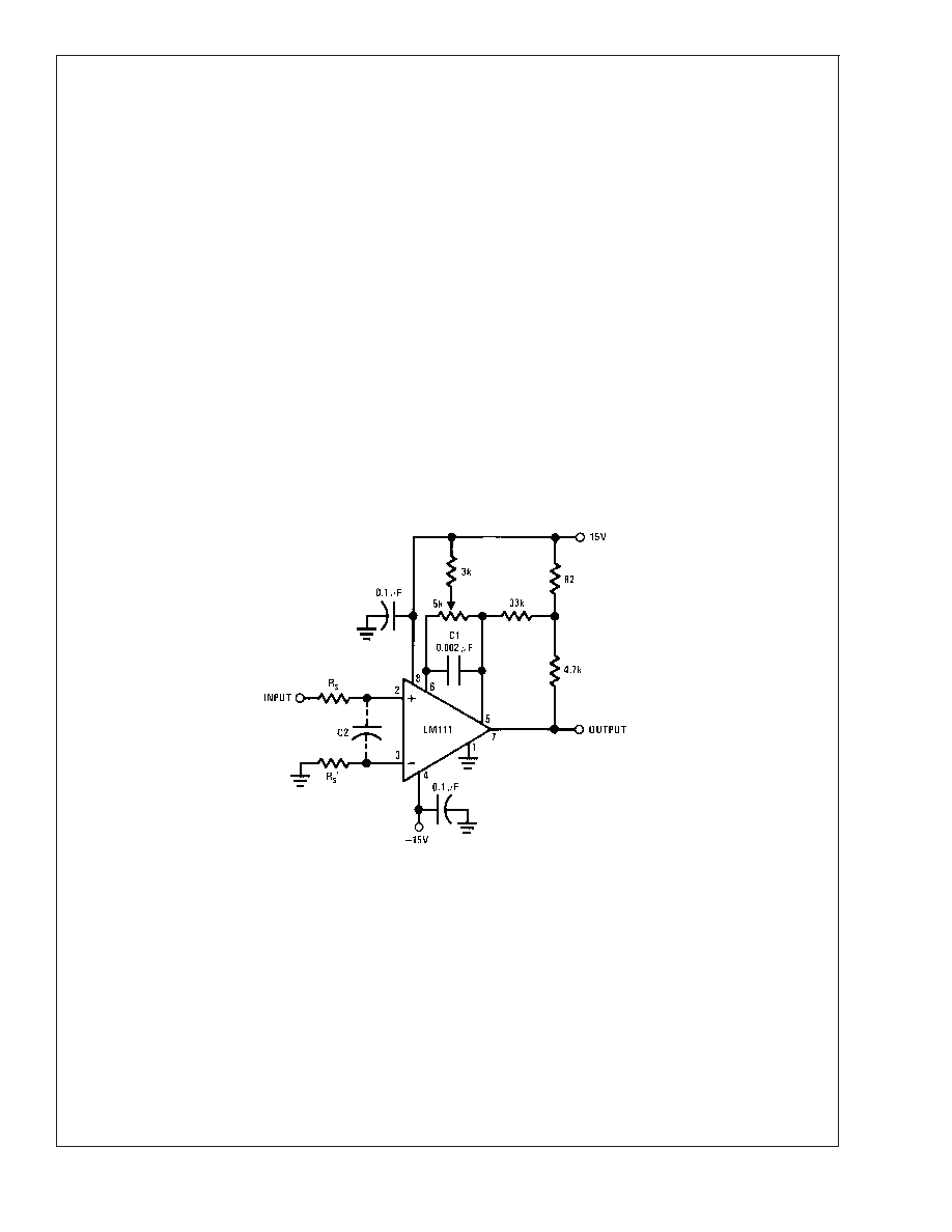
7.
When both inputs of the LM111 are connected to active
signals, or if a high-impedance signal is driving the
positive input of the LM111 so that positive feedback
would be disruptive, the circuit of Figure 1 is ideal. The
positive feedback is to pin 5 (one of the offset adjust-
ment pins). It is sufficient to cause 1 to 2 mV hysteresis
and sharp transitions with input triangle waves from a
few Hz to hundreds of kHz. The positive-feedback signal
across the 82
resistor swings 240 mV below the posi-
tive supply. This signal is centered around the nominal
voltage at pin 5, so this feedback does not add to the
V
OS of the comparator. As much as 8 mV of VOS can be
trimmed out, using the 5 k
pot and 3 k resistor as
shown.
8.
These application notes apply specifically to the LM111
and LF111 family of comparators, and are applicable to
all high-speed comparators in general, (with the excep-
tion that not all comparators have trim pins).
20128529
Pin connections shown are for LM111H in the H08 hermetic package
FIGURE 1. Improved Positive Feedback
LM1
1
1QML
www.national.com
17
相关PDF资料 |
PDF描述 |
|---|---|
| 5962P0052401VHA | COMPARATOR, 4000 uV OFFSET-MAX, 200 ns RESPONSE TIME, CDFP10 |
| 5962P9853901VGA | OP-AMP, 6000 uV OFFSET-MAX, 15 MHz BAND WIDTH, MBCY8 |
| 5962P9853901VPA | OP-AMP, 6000 uV OFFSET-MAX, 15 MHz BAND WIDTH, CDIP8 |
| 5962P9853901VZA | OP-AMP, 6000 uV OFFSET-MAX, 15 MHz BAND WIDTH, CDSO10 |
| 5962R1122201VZA | OP-AMP, 2000 uV OFFSET-MAX, 2.7 MHz BAND WIDTH, CDSO10 |
相关代理商/技术参数 |
参数描述 |
|---|---|
| 5962P9951701VXA | 功能描述:线性稳压器 - 标准 RoHS:否 制造商:STMicroelectronics 输出类型: 极性: 输出电压:1.8 V 输出电流:150 mA 负载调节: 最大输入电压:5.5 V 线路调整率: 最大工作温度:+ 125 C 安装风格:SMD/SMT 封装 / 箱体:SOT-323-5L |
| 5962P9951708VXA | 制造商:Texas Instruments 功能描述:5962P9951708VXA - Rail/Tube |
| 5962R0050101VXA | 功能描述:基准电压& 基准电流 RoHS:否 制造商:STMicroelectronics 产品:Voltage References 拓扑结构:Shunt References 参考类型:Programmable 输出电压:1.24 V to 18 V 初始准确度:0.25 % 平均温度系数(典型值):100 PPM / C 串联 VREF - 输入电压(最大值): 串联 VREF - 输入电压(最小值): 分流电流(最大值):60 mA 最大工作温度:+ 125 C 封装 / 箱体:SOT-23-3L 封装:Reel |
| 5962R0051501VHA | 制造商:Analog Devices 功能描述:COMPARATOR SGL 5V/10V 10PIN FLATPACK - Rail/Tube |
| 5962R0051501VPA |
发布紧急采购,3分钟左右您将得到回复。