- 您现在的位置:买卖IC网 > PDF目录20635 > 71M6521DE-IGT/F (Maxim Integrated)IC ENERGY METER 16K FLASH 64LQFP PDF资料下载
参数资料
| 型号: | 71M6521DE-IGT/F |
| 厂商: | Maxim Integrated |
| 文件页数: | 43/107页 |
| 文件大小: | 0K |
| 描述: | IC ENERGY METER 16K FLASH 64LQFP |
| 产品培训模块: | Lead (SnPb) Finish for COTS Obsolescence Mitigation Program |
| 标准包装: | 160 |
| 系列: | Single Converter Technology® |
| 测量误差: | 0.4% |
| 电源电压: | 3 V ~ 3.6 V |
| 测量仪表类型: | 单相,双相 |
| 工作温度: | -40°C ~ 85°C |
| 安装类型: | 表面贴装 |
| 封装/外壳: | 64-LQFP |
| 供应商设备封装: | 64-LQFP(10x10) |
| 包装: | 管件 |
第1页第2页第3页第4页第5页第6页第7页第8页第9页第10页第11页第12页第13页第14页第15页第16页第17页第18页第19页第20页第21页第22页第23页第24页第25页第26页第27页第28页第29页第30页第31页第32页第33页第34页第35页第36页第37页第38页第39页第40页第41页第42页当前第43页第44页第45页第46页第47页第48页第49页第50页第51页第52页第53页第54页第55页第56页第57页第58页第59页第60页第61页第62页第63页第64页第65页第66页第67页第68页第69页第70页第71页第72页第73页第74页第75页第76页第77页第78页第79页第80页第81页第82页第83页第84页第85页第86页第87页第88页第89页第90页第91页第92页第93页第94页第95页第96页第97页第98页第99页第100页第101页第102页第103页第104页第105页第106页第107页
�� �
�
 �
�71M6521DE/DH/FE� Data� Sheet�
�EEPROM Interface�
�The� 71M6521DE/DH/FE� provides� hardware� support� for� either� type� of� EEPROM� interface,� a� two-pin� interface� and� a�
�three-pin� interface.� The� interfaces� use� the� EECTRL� and� EEDATA� registers� for� communication.�
�Two-Pin� EEPROM� Interface�
�The� dedicated� 2-pin� serial� interface� communicates� with� external� EEPROM� devices.� The� interface� is� multiplexed� onto�
�pins� DIO4� (SCK)� and� DIO5� (SDA)� controlled� by� the� DIO_EEX� bit� I/O� RAM� (see� I/O� RAM� Table).� The� MPU�
�communicates� with� the� interface� through� two� SFR� registers:� EEDATA� and� EECTRL� .� If� the� MPU� wishes� to� write� a� byte�
�of� data� to� EEPROM,� it� places� the� data� in� EEDATA� and� then� writes� the� ‘Transmit’� command� (CMD� =� 0011)� to� EECTRL� .�
�This� initiates� the� transmit� operation.� The� transmit� operation� is� finished� when� the� BUSY� bit� falls.� Interrupt� INT5� is� also�
�asserted� when� BUSY� falls.� The� MPU� can� then� check� the� RX_ACK� bit� to� see� if� the� EEPROM� acknowledged� the�
�transmission.�
�A� byte� is� read� by� writing� the� ‘Receive’� command� (CMD� =� 0001)� to� EECTRL� and� waiting� for� the� BUSY� bit� to� fall.� Upon�
�completion,� the� received� data� is� in� EEDATA� .� The� serial� transmit� and� receive� clock� is� 78kHz� during� each� transmission,�
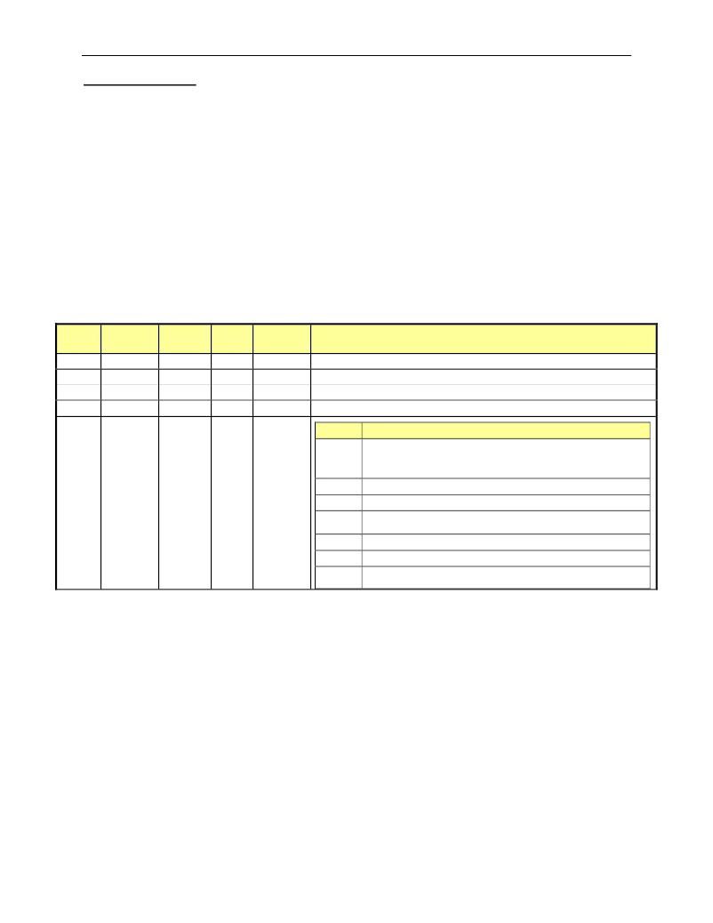
�and� the� clock� is� held� in� a� high� state� until� the� next� transmission.� The� bits� in� EECTRL� are� shown� in� Table� 57.�
�The� EEPROM� interface� can� also� be� operated� by� controlling� the� DIO4� and� DIO5� pins� directly� (“bit-banging”).�
�However,� controlling� DIO4� and� DIO5� directly� is� discouraged,� because� it� may� tie� up� the� MPU� to� the� point�
�where� it� may� become� too� busy� to� process� interrupts� .�
�Status�
�Bit�
�7�
�6�
�5�
�4�
�Name�
�ERROR�
�BUSY�
�RX_ACK�
�TX_ACK�
�Read/�
�Write�
�R�
�R�
�R�
�R�
�Reset�
�State�
�0�
�0�
�1�
�1�
�Polarity�
�Positive�
�Positive�
�Negative�
�Negative�
�Description�
�1� when� an� illegal� command� is� received.�
�1� when� serial� data� bus� is� busy.�
�0� indicates� that� the� EEPROM� sent� an� ACK� bit.�
�0� indicates� when� an� ACK� bit� has� been� sent� to� the� EEPROM�
�CMD�
�0000�
�Operation�
�No-op.� Applying� the� no-op� command� will� stop� the� I� 2� C� clock�
�(SCK,� DIO4).� Failure� to� issue� the� no-op� command� will� keep�
�the� SCK� signal� toggling.�
�3-0�
�CMD�
�[3:0]�
�W�
�0�
�Positive,�
�see� CMD�
�Table�
�0001�
�0011�
�0101�
�Receive� a� byte� from� EEPROM� and� send� ACK.�
�Transmit� a� byte� to� EEPROM.�
�Issue� a� ‘STOP’� sequence.�
�0110�
�1001�
�Others�
�Receive� the� last� byte� from� EEPROM,� do� not� send� ACK.�
�Issue� a� ‘START’� sequence.�
�No� Operation,� set� the� ERROR� bit.�
�Table� 57:� EECTRL� Status� Bits�
�Rev� 3�
�Page:� 43� of� 107�
�相关PDF资料 |
PDF描述 |
|---|---|
| F930J107KCC | CAP TANT 100UF 6.3V 10% 2312 |
| MAX8631XETI+ | IC LED DRVR WHITE BCKLGT 28-TQFN |
| 78M6612-IM/F | IC POWER MEASUREMENT AC 68-QFN |
| GEM15DRTF | CONN EDGECARD 30POS DIP .156 SLD |
| VI-2NP-EW-B1 | CONVERTER MOD DC/DC 13.8V 100W |
相关代理商/技术参数 |
参数描述 |
|---|---|
| 71M6521DE-IGTR/F | 功能描述:计量片上系统 - SoC Residential Energy Meter IC RoHS:否 制造商:Maxim Integrated 核心:80515 MPU 处理器系列:71M6511 类型:Metering SoC 最大时钟频率:70 Hz 程序存储器大小:64 KB 数据 RAM 大小:7 KB 接口类型:UART 可编程输入/输出端数量:12 片上 ADC: 安装风格:SMD/SMT 封装 / 箱体:LQFP-64 封装:Reel |
| 71M6521DE-IGTR/F1 | 功能描述:计量片上系统 - SoC RoHS:否 制造商:Maxim Integrated 核心:80515 MPU 处理器系列:71M6511 类型:Metering SoC 最大时钟频率:70 Hz 程序存储器大小:64 KB 数据 RAM 大小:7 KB 接口类型:UART 可编程输入/输出端数量:12 片上 ADC: 安装风格:SMD/SMT 封装 / 箱体:LQFP-64 封装:Reel |
| 71M6521DE-IM/F | 功能描述:计量片上系统 - SoC Residential Energy Meter IC RoHS:否 制造商:Maxim Integrated 核心:80515 MPU 处理器系列:71M6511 类型:Metering SoC 最大时钟频率:70 Hz 程序存储器大小:64 KB 数据 RAM 大小:7 KB 接口类型:UART 可编程输入/输出端数量:12 片上 ADC: 安装风格:SMD/SMT 封装 / 箱体:LQFP-64 封装:Reel |
| 71M6521DEIM-DB | 制造商:Maxim Integrated Products 功能描述:Development Boards & Kits - 8051 71M6521DE Demo Brd |
| 71M6521DE-IMR/F | 功能描述:计量片上系统 - SoC Residential Energy Meter IC RoHS:否 制造商:Maxim Integrated 核心:80515 MPU 处理器系列:71M6511 类型:Metering SoC 最大时钟频率:70 Hz 程序存储器大小:64 KB 数据 RAM 大小:7 KB 接口类型:UART 可编程输入/输出端数量:12 片上 ADC: 安装风格:SMD/SMT 封装 / 箱体:LQFP-64 封装:Reel |
发布紧急采购,3分钟左右您将得到回复。