- 您现在的位置:买卖IC网 > PDF目录68811 > 71M6542F-IGT/F (MAXIM INTEGRATED PRODUCTS INC) SPECIALTY ANALOG CIRCUIT, PQFP100 PDF资料下载
参数资料
| 型号: | 71M6542F-IGT/F |
| 厂商: | MAXIM INTEGRATED PRODUCTS INC |
| 元件分类: | 模拟信号调理 |
| 英文描述: | SPECIALTY ANALOG CIRCUIT, PQFP100 |
| 封装: | LEAD FREE, LQFP-100 |
| 文件页数: | 84/165页 |
| 文件大小: | 2208K |
| 代理商: | 71M6542F-IGT/F |
第1页第2页第3页第4页第5页第6页第7页第8页第9页第10页第11页第12页第13页第14页第15页第16页第17页第18页第19页第20页第21页第22页第23页第24页第25页第26页第27页第28页第29页第30页第31页第32页第33页第34页第35页第36页第37页第38页第39页第40页第41页第42页第43页第44页第45页第46页第47页第48页第49页第50页第51页第52页第53页第54页第55页第56页第57页第58页第59页第60页第61页第62页第63页第64页第65页第66页第67页第68页第69页第70页第71页第72页第73页第74页第75页第76页第77页第78页第79页第80页第81页第82页第83页当前第84页第85页第86页第87页第88页第89页第90页第91页第92页第93页第94页第95页第96页第97页第98页第99页第100页第101页第102页第103页第104页第105页第106页第107页第108页第109页第110页第111页第112页第113页第114页第115页第116页第117页第118页第119页第120页第121页第122页第123页第124页第125页第126页第127页第128页第129页第130页第131页第132页第133页第134页第135页第136页第137页第138页第139页第140页第141页第142页第143页第144页第145页第146页第147页第148页第149页第150页第151页第152页第153页第154页第155页第156页第157页第158页第159页第160页第161页第162页第163页第164页第165页
v1.1
2008–2011 Teridian Semiconductor Corporation
25
SUM_SAMPS[12:0] supports an accumulation scheme where the incremental energy values from up to
SUM_SAMPS[12:0] multiplexer frames are added up over one accumulation interval. The integration time
for each energy output is, for example, SUM_SAMPS[12:0]/2520.6 (with MUX_DIV[3:0] = 011, I/O RAM
0x2100[7:4] and FIR_LEN[1:0] = 10, I/O RAM 0x210C[2:1]). CE hardware issues the XFER_BUSY interrupt
when the accumulation is complete.
2.3.3
CE Communication with the MPU
The CE outputs six signals to the MPU: CE_BUSY, XFER_BUSY, XPULSE, YPULSE, WPULSE and
VPULSE. These are connected to the MPU interrupt service. CE_BUSY indicates that the CE is actively
processing data. This signal occurs once every multiplexer frame. XFER_BUSY indicates that the CE is
updating to the output region of the CE RAM, which occurs whenever an accumulation cycle has been
completed. Both, CE_BUSY and XFER_BUSY are cleared when the CE executes a HALT instruction.
XPULSE, YPULSE, VPULSE and WPULSE can be configured to interrupt the MPU and indicate sag
failures, zero crossings of the mains voltage, or other significant events. Additionally, these signals can
be connected directly to DIO pins to provide direct outputs for the CE. Interrupts associated with these
signals always occur on the leading edge (see “External” interrupt source No. 2 in Figure 16).
2.3.4
Meter Equations
The 71M6541D/F and 71M6542F provide hardware assistance to the CE in order to support various meter
equations. This assistance is controlled through I/O RAM register EQU[2:0] (equation assist). The Compute
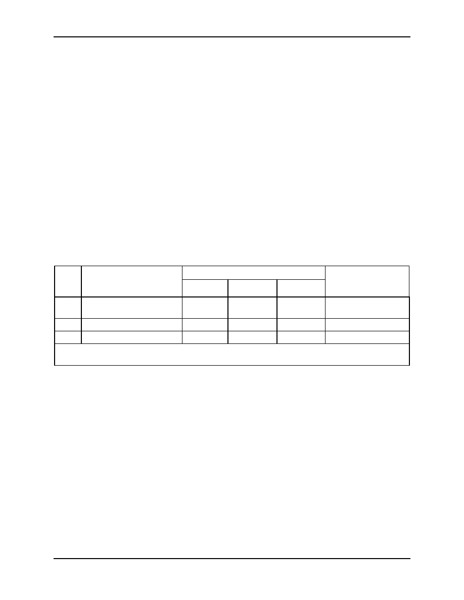
Engine (CE) firmware for industrial configurations can implement the equations listed in Table 8. EQU[2:0]
specifies the equation to be used based on the meter configuration and on the number of phases used for
metering.
Table 8: Inputs Selected in Multiplexer Cycles
EQU
Description
Wh and VARh formula
Recommended
Multiplexer
Sequence
Element 0
Element 1
Element 2
0
1-element, 2-W, 1
φ with
neutral current sense
VA
IA
VA
IB1
N/A
IA VA IB
1
1-element, 3-W, 1
φ
VA(IA-IB)/2
N/A
IA VA IB
2
2-element, 3-W, 3
φ Delta
VA
IA
VB
IB
N/A
IA VA IB VB
Note:
1.
Optionally, IB may be used to measure neutral current
71M6542F only
2.3.5
Real-Time Monitor (RTM)
The CE contains a Real-Time Monitor (RTM), which can be programmed to monitor four selectable
XRAM locations at full sample rate. The four monitored locations, as selected by the I/O RAM registers
RTM0[9:8], RTM0[7:0], RTM1[9:8], RTM1[7:0], RTM2[9:8], RTM2[7:0], RTM3[9:8], and RTM3[7:0], are
serially output to the TMUXOUT pin via the digital output multiplexer at the beginning of each CE code
pass. The RTM can be enabled and disabled with control bit RTM_E (I/O RAM 0x2106[1]). The RTM
output is clocked by CKTEST. Each RTM word is clocked out in 35 CKCE cycles (1 CKCE cycle is
equivalent to 203 ns) and contains a leading flag bit. See Figure 10 for the RTM output format. RTM is
low when not in use.
Figure 11 summarizes the timing relationships between the input MUX states, the CE_BUSY signal, and
the RTM serial output stream. In this example, MUX_DIV[3:0] = 4 (I/O RAM 0x2100[7:4]) and
FIR_LEN[1:0] = 10 (I/O RAM 0x210C[1]), (384), resulting in 4 ADC conversions. An ADC conversion
always consumes an integer number of CK32 clocks. Followed by the conversions is a single CK32
cycle.
Figure 11 also shows that the RTM serial data stream begins transmitting at the beginning of state S.
RTM, consisting of 140 CK cycles, always finishes before the next CE code pass starts.
相关PDF资料 |
PDF描述 |
|---|---|
| 71M6542G-IGTR/F | SPECIALTY ANALOG CIRCUIT, PQFP100 |
| 71M6541G-IGTR/F | SPECIALTY ANALOG CIRCUIT, PQFP64 |
| 71M6541F-IGTR/F | SPECIALTY ANALOG CIRCUIT, PQFP64 |
| 71M6541D-IGTR/F | SPECIALTY ANALOG CIRCUIT, PQFP64 |
| 71M6542F-IGTR/F | SPECIALTY ANALOG CIRCUIT, PQFP100 |
相关代理商/技术参数 |
参数描述 |
|---|---|
| 71M6542F-IGTR/F | 功能描述:计量片上系统 - SoC Precision Energy Meter IC RoHS:否 制造商:Maxim Integrated 核心:80515 MPU 处理器系列:71M6511 类型:Metering SoC 最大时钟频率:70 Hz 程序存储器大小:64 KB 数据 RAM 大小:7 KB 接口类型:UART 可编程输入/输出端数量:12 片上 ADC: 安装风格:SMD/SMT 封装 / 箱体:LQFP-64 封装:Reel |
| 71M6542FT-IGT/F | 制造商:Maxim Integrated Products 功能描述:1-PHASE SOC 128KB WITH PREC TEMP SENSOR - Rail/Tube |
| 71M6542FT-IGTR/F | 制造商:Maxim Integrated Products 功能描述:1-PHASE SOC, 64KB FLASH, PRES TEMP SENSOR - Tape and Reel |
| 71M6542G | 制造商:未知厂家 制造商全称:未知厂家 功能描述:71M6541D/71M6541F/71M6541G/71M6542F/71M6542G 是 TeridianTM 的第4 代高集成度单相电表SoC |
| 71M6542G-IGT/F | 功能描述:计量片上系统 - SoC 1-Phase Metering SOC with 128KB Flash RoHS:否 制造商:Maxim Integrated 核心:80515 MPU 处理器系列:71M6511 类型:Metering SoC 最大时钟频率:70 Hz 程序存储器大小:64 KB 数据 RAM 大小:7 KB 接口类型:UART 可编程输入/输出端数量:12 片上 ADC: 安装风格:SMD/SMT 封装 / 箱体:LQFP-64 封装:Reel |
发布紧急采购,3分钟左右您将得到回复。