- 您现在的位置:买卖IC网 > PDF目录24617 > 9161A-01CW16WLF (INTEGRATED DEVICE TECHNOLOGY INC) 120 MHz, VIDEO CLOCK GENERATOR, PDSO16 PDF资料下载
参数资料
| 型号: | 9161A-01CW16WLF |
| 厂商: | INTEGRATED DEVICE TECHNOLOGY INC |
| 元件分类: | 时钟产生/分配 |
| 英文描述: | 120 MHz, VIDEO CLOCK GENERATOR, PDSO16 |
| 封装: | 0.300 INCH, SOIC-16 |
| 文件页数: | 9/15页 |
| 文件大小: | 539K |
| 代理商: | 9161A-01CW16WLF |
3
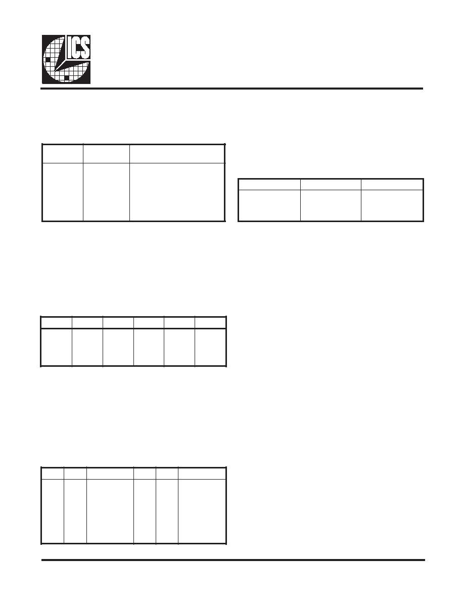
ICS9161A
Register Definitions
The register file consists of the following six registers:
Register Addressing
As seen in the VCLK Selection table, OE acts to tristate the
output. The PD# pin forces the VCLK signal high while
powering down the part. The EXTCLK pin will only be
multiplexed in when EXTSEL and SEL0 are logic 0 and SEL1
is a logic 1.
The memory clock outputs are controlled by PD# and OE
as follows:
The Clock Select pins SEL0 and SEL1 have two purposes. In
serial programming mode, these pins act as the clock and data
pins. New data bits come in on SEL1 and these bits are
clocked in by a signal on SEL0. While these pins are acquiring
new information, the VCLK signal remains unchanged. When
SEL0 and SEL1 are acting as register selects, a time-out
interval is required to determine whether the user is selecting
a new register or wants to program the part. During this initial
time-out, the VCLK signal remains at its previous frequency.
At the end of this time-out interval, a new register is selected.
A second time-out interval is required to allow the VCO to
settle to its new value. During this period of time, typically
5ms, the input reference signal is multiplexed to the VCLK
signal.
When MCLK or the active VCLK register is being re-
programmed, then the reference signal is multiplexed glitch-
free to the output during the first time-out interval. A second
time-Register out interval is also required to allow the VCO
to settle. During this period, the reference signal is
multiplexed to the appropriate output signal.
The ICS9161A places the three video clock registers and the
memory clock register in a known state upon power-up. The
registers are initialized based on the state of the INIT1 and
INIT0 pins at application of power to the device. The INIT pins
must ramp up with VDD if a logical 1 on either pin is required.
These input pins are internally pulled down and will default to
a logical 0 if left unconnected.
The registers are initialized as follows:
Register Initialization
Register Selection
When the ICS9161A is operating, the video clock output is
controlled with a combination of the SEL0, SEL1, PD# and
OE pins. The video clock is also multiplexed to an external
clock (EXTCLK) which can be selected with the EXTSEL
pin. The VCLK Selection Table shows how VCLK is selected.
VCLK Selection
1
T
I
N
I0
T
I
N
IG
E
R
M0
G
E
R1
G
E
R2
G
E
R
0
1
0
1
0
1
0
5
.
2
3
0
.
0
4
0
5
3
.
0
5
4
6
.
6
5
7
1
.
5
2
5
7
1
.
5
2
0
.
0
4
0
.
0
4
2
3
.
8
2
3
.
8
2
3
.
8
2
0
5
3
.
0
5
2
3
.
8
2
3
.
8
2
3
.
8
2
0
5
3
.
0
5
E
O#
D
PL
E
S
T
X
E1
L
E
S0
L
E
SK
L
C
V
0
1
x
0
1
x
0
1
x
0
1
x
0
1
0
x
1
e
t
a
t
s
i
r
T
h
g
i
H
d
e
c
r
o
F
0
G
E
R
1
G
E
R
K
L
C
T
X
E
2
G
E
R
2
G
E
R
E
O#
D
PK
L
C
M
0
1
x
1
0
e
t
a
t
s
i
r
T
G
E
R
M
N
W
D
R
W
P
MCLK Selection
s
e
r
d
A
)
0
A
-
2
A
(
r
e
t
s
i
g
e
Rn
o
i
t
i
n
i
f
e
D
0
1
0
1
0
1
0
1
0
1
0
G
E
R
1
G
E
R
2
G
E
R
G
E
R
M
N
W
D
R
W
P
G
E
R
L
T
N
C
1
r
e
t
s
i
g
e
R
k
c
o
l
C
o
e
d
i
V
2
r
e
t
s
i
g
e
R
k
c
o
l
C
o
e
d
i
V
3
r
e
t
s
i
g
e
R
k
c
o
l
C
o
e
d
i
V
r
e
t
s
i
g
e
R
y
r
o
m
e
M
e
d
o
m
n
w
o
d
-
r
e
w
o
P
r
o
f
r
o
s
i
v
i
D
r
e
t
s
i
g
e
R
l
o
r
t
n
o
C
相关PDF资料 |
PDF描述 |
|---|---|
| 9161A-01CW16W | 120 MHz, VIDEO CLOCK GENERATOR, PDSO16 |
| 9162C | 2M X 32 FAST PAGE DRAM MODULE, 60 ns, SMA72 |
| 9163901MFA | QUAD LINE DRIVER, CDFP16 |
| 9163901MEA | QUAD LINE DRIVER, CDIP16 |
| 9163901M2A | QUAD LINE DRIVER, CQCC20 |
相关代理商/技术参数 |
参数描述 |
|---|---|
| 9-161A-R | 制造商:Cinch Connectors 功能描述: |
| 9161-CHR-BULK | 制造商:Belden Inc 功能描述: |
| 9-161-L | 制造商:Cinch Connectors 功能描述: |
| 9-161-R | 制造商:Cinch Connectors 功能描述:Conn Terminal Strip 9 POS 11.13mm Crimp ST Cable Mount |
| 9162 | 功能描述:PROTO-BOARD 14/16PIN SOIC SMD RoHS:是 类别:原型开发产品 >> 适配器,可互换接口板 系列:9000, Surfboards® 标准包装:1 系列:- 原型板类型:- Package Accepted:- 尺寸/尺寸:- 位置数:- 孔直径:- 板厚度:- 材质:- |
发布紧急采购,3分钟左右您将得到回复。