- 您现在的位置:买卖IC网 > PDF目录122717 > 935261475512 (NXP SEMICONDUCTORS) 8 CHANNEL(S), 500K bps, SERIAL COMM CONTROLLER, PQCC84 PDF资料下载
参数资料
| 型号: | 935261475512 |
| 厂商: | NXP SEMICONDUCTORS |
| 元件分类: | 微控制器/微处理器 |
| 英文描述: | 8 CHANNEL(S), 500K bps, SERIAL COMM CONTROLLER, PQCC84 |
| 封装: | PLASTIC, MO-047AF, SOT-189-3, LCC-84 |
| 文件页数: | 6/59页 |
| 文件大小: | 383K |
| 代理商: | 935261475512 |
第1页第2页第3页第4页第5页当前第6页第7页第8页第9页第10页第11页第12页第13页第14页第15页第16页第17页第18页第19页第20页第21页第22页第23页第24页第25页第26页第27页第28页第29页第30页第31页第32页第33页第34页第35页第36页第37页第38页第39页第40页第41页第42页第43页第44页第45页第46页第47页第48页第49页第50页第51页第52页第53页第54页第55页第56页第57页第58页第59页
Philips Semiconductors
Product specification
SC28L198
Octal UART for 3.3V and 5V supply voltage
1999 Jan 14
14
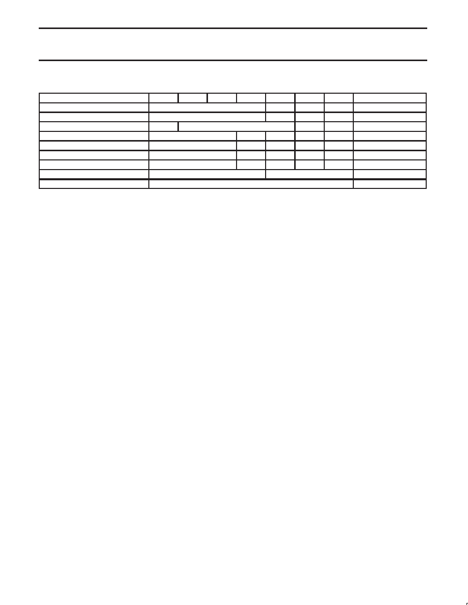
Table 1. Interrupt Arbitration Priority
Type
B9
B8
B7
B6
B5
B4
B3
Bits 2:0
Receiver w/o error
RxFIFO Byte Count –1
0
0
1
Channel No
Receiver w/ error
RxFIFO Byte Count –1
1
0
1
Channel No
Transmitter
0
TxFIFO Byte Count –1
0
0
Channel No
Change of Break
Programmed Field
0
0
1
0
Channel No
Change of State
Programmed Field
0
1
1
0
Channel No
Xon/Xoff
Programmed Field
0
1
1
1
Channel No
Address Recognition
Programmed Field
0
0
1
1
Channel No
Receiver Watch-dog
RxFIFO Byte Count –1
As RxFIFO Above
Channel No
Threshold
Bits 6:0 of Interrupt Control Register
000
Note several characteristics of the above table in bits 6:3. These
bits contain the identification of the bidding source as indicated
below:
x001
Receiver without error
x101
Receiver with error
xx00
Transmitter
0010
Change of Break
0110
Change of State on I/O Ports
0111
Xon/Xoff Event
0011
Address Recognition
The codes form bits 6:3 drive part of the interrupt vector modification
and the Global Interrupt Type Register. The codes are unique to
each source type and Identify them completely. The channel
numbering progresses from ”a” to ”d” as the binary numbers 000 to
011 and identify the interrupting channel uniquely. As the channels
arbitrate ”d” will have the highest bidding value and ”a” the lowest
Note that the transmitter byte count is off–set from that of the
receiver by one bit. This is to give the receiver more authority in the
arbitration since and over–run receiver corrupts the message but an
under–run transmitter is not harmful. This puts some constraints on
how the threshold value is selected. If a threshold is chosen that
has its MSB set to one then a transmitter can never generate an
interrupt! Of course the counter point to this is the desire to set the
interrupt threshold high so interrupts occur only when a maximum or
near maximum number of characters may be transferred.
To give some control over this dilemma control bits have been
provided in the MR0 and MR2 registers of each channel to
individually control when a receiver or transmitter may interrupt. The
use of these bits will prevent a receiver or a transmitter from
entering the arbitration process even though its FIFO fill level is
above that indicated by the threshold value set. The bits in the MR0
and MR2 register are named TxINT (MR0[5:4]) and RxINT
(MR2[3:2])
The watch-dog is included in the table above to show that it affects
the arbitration. It does not have an identity of its own. A barking
watch-dog will prevent any other source type from entering the
arbitration process except enabled receivers. The threshold is
effectively set to zero when any watch-dog times out. The receivers
arbitrate among them selves and the one with the highest fill level
will win the process. Note that the receiver wining the bid may not
be the one that caused the watch-dog to bark.
The fields labeled ”Programmed Field” are the contents of the
Bidding Control Registers, BCRs, for these sources. Setting these
bits to high values can elevate the interrupt importance of the
sources they represent to values almost as high as a full receiver.
For example a COS event may be very important when it represents
the DSR (Data Set Ready) signal from the modem. In this case its
arbitration value should be high. Once the DSR is recognized then
its arbitration value could be reduced or turned off.
There is a single arbiter interrupt number that is not associated with
any of the UART channels. It is the ”Threshold Value” and is
comprised of 7 bits from the Interrupt Control Register, ICR, and
three zeros in the channel field. It is only when one or more of
the enabled interrupt sources generates a arbitration value
larger than the threshold value that the IRQN will be asserted.
When the threshold bidding value is larger than any other bidding
value then the IRQN will be withdrawn. In this condition the CIR will
be loaded with if the IRQN or ”Update CIR” command is asserted.
Because the channels are numbered from 0 to 3 ( A to D) channel 3
will win the bid when all other parts of the bid are equal.
Note: Based on this coding for the receiver and transmitter, a
transmitter would not win a bid in the situation where the Count
Field = 0 unless the threshold value is equal or less than
0000011. A single empty slot is left in the TxFIFO or a single
filled slot in the RxFIFO will bid with a value of zero.
MODES OF OPERATION
Major Modes
Four major modes of operation (normal, auto echo, local loop back
and remote loop back) are provided and are controlled by MR2[7:6].
Three of these may be considered diagnostic. See the MR2 register
description.
The normal mode is the usual mode for data I/O operation. Most
reception and transmission will use the normal mode.
In the auto echo mode, the transmitter automatically re-transmits
any character captured by the channel’s receiver. The receiver 1x
clock is used for the transmitter. This mode returns the received
data back to the sending station one bit time delayed from its
departure. Receiver to host communication is normal. Host to
transmitter communication has no meaning.
In the local loop back mode (used for diagnostic purposes) the
transmitter is internally connected to the receiver input. The
transmitter 1x clock used for the receiver. The RxD input pin is
ignored and the transmitter TxD output pin is held high. This
configuration allows the transmitter to send data to the receiver
without any external parameters to affect the transmission of data.
All status bits, interrupt conditions and processor interface operate
normally. It is recommended that this mode be used when
initially verifying processor to UART interface. The
communication between the transmitter and receiver is entirely
within the UART – it is essentially ”talking to itself”.
相关PDF资料 |
PDF描述 |
|---|---|
| 9LPRS365BKLF | SPECIALTY MICROPROCESSOR CIRCUIT, PQCC64 |
| 91W-G28AC-6-CG9 | SINGLE COLOR DISPLAY CLUSTER, GREEN, 7.1 mm |
| 91W-G5AC-6-CW0 | SINGLE COLOR DISPLAY CLUSTER, GREEN, 7.1 mm |
| 94W-EAY2-S0 | SINGLE COLOR LED, AMBER, 8.5 mm |
| 94W-EAY28H-CA0 | SINGLE COLOR LED, AMBER, 8.5 mm |
相关代理商/技术参数 |
参数描述 |
|---|---|
| 935262025112 | 制造商:NXP Semiconductors 功能描述:SUB ONLY IC |
| 935262217118 | 制造商:NXP Semiconductors 功能描述:Real Time Clock Serial 8-Pin SO T/R |
| 935264217557 | 制造商:NXP Semiconductors 功能描述:SUB ONLY IC |
| 935267356112 | 制造商:NXP Semiconductors 功能描述:IC TEA1507PN |
| 935268081112 | 制造商:NXP Semiconductors 功能描述:SUB ONLY IC |
发布紧急采购,3分钟左右您将得到回复。