- 您现在的位置:买卖IC网 > PDF目录67354 > A1174EEWLT-P MAGNETIC FIELD SENSOR-HALL EFFECT, -5.5-5.5mT, 300mV, RECTANGULAR, SURFACE MOUNT PDF资料下载
参数资料
| 型号: | A1174EEWLT-P |
| 元件分类: | 磁阻传感器 |
| 英文描述: | MAGNETIC FIELD SENSOR-HALL EFFECT, -5.5-5.5mT, 300mV, RECTANGULAR, SURFACE MOUNT |
| 封装: | 1.50 X 2 MM, 0.40 MM HEIGHT, LEAD FREE, DFN-6 |
| 文件页数: | 13/13页 |
| 文件大小: | 316K |
| 代理商: | A1174EEWLT-P |
Ultrasensitive Hall Effect Latch
with Internally or Externally Controlled Sample and Sleep Periods
for Track Ball and Scroll Wheel Applications
A1174
9
Allegro MicroSystems, Inc.
115 Northeast Cutoff
Worcester, Massachusetts 01615-0036 U.S.A.
1.508.853.5000; www.allegromicro.com
allows stabilization prior to the IC sampling and data latching on
the falling edge of the timing pulse. The output during the sleep
time, tsleep, is latched in the last sampled state.
External Clock Mode
Applying a voltage greater than
Vth(HIGH) to both clock pins puts the device into the awake state
(without automatic cycling through the sleep state). The device
uses the maximum defined supply current, reaching maximum
power consumption.
Applying a voltage greater than Vth(HIGH) to the EXTERNAL_
CLK pin and a voltage lower than Vth(LOW) to the DUAL_CLK
pin puts the device into the sleep state (without automatic cycling
through the awake state), and latches the device output in the
output state determined during the prior awake state.
The duration of the awake and sleep periods can be controlled
externally by applying a voltage greater than Vth(HIGH) to the
EXTERNAL_CLK pin and applying an external clock to the
DUAL_CLK pin. The user can define the input sampling time
and frequency to reach a target consumption current level, but the
minimum sample time must remain longer than tawake_ext. Note
that the device should be periodically put into the awake state in
order to update the device output state.
State Transition Delay, text_delay, appears as the time between
an external clock transition and the resulting transition of the
device between the awake and the sleep state. This is illustrated
in figure 5.
Dual Clock Mode
When the EXTERNAL_CLK pin is left
floating, or is grounded, and the DUAL_CLK pin is pulled to
a voltage greater than Vth(HIGH), the device enters Dual Clock
mode. Figure 6 gives an overview of the device operation algo-
rithm in Dual Clock mode.
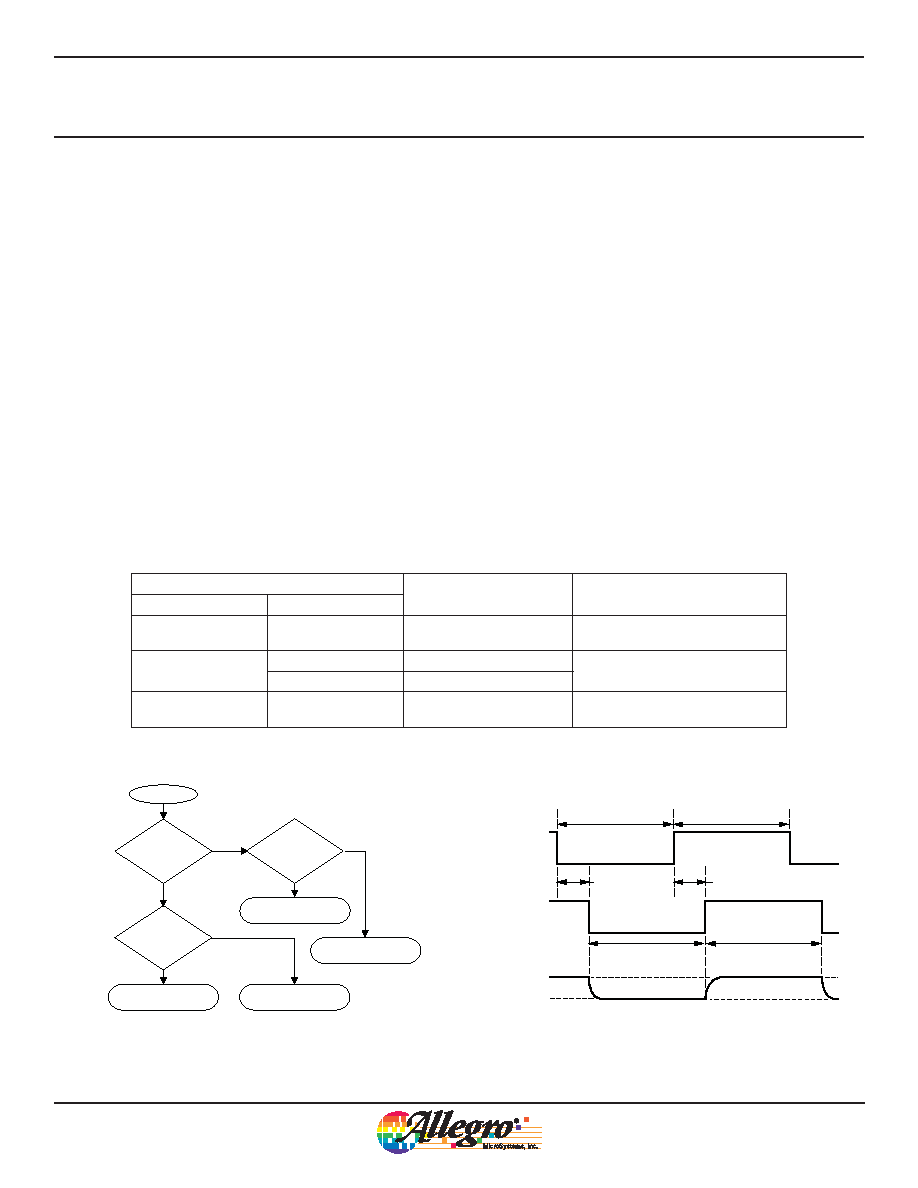
Figure 5. External Clock mode clocking; tdelay_ext corresponding to the
device transition delay into the awake or sleep states after an external
clock transition
External
Clocking
Internal
Clocking
tdelay_ext
tsleep_ext
tawake_ext
tdelay_ext
Device Awake State
Device Sleep State
Supply
Current
IDD(EN)
IDD(DIS)
Table 1. Clock Mode Selection Options
Connection
Mode
Description
EXTERNAL_CLK Pin
DUAL_CLK Pin
Low / NC
Normal Clock
Awake and sleep state durations
defined by device internal clock
High
External Clock, Awake State
Awake and sleep state durations
defined by external clock
Low
External Clock, Sleep State
Low / NC
High
Dual Clock
Awake and sleep state durations
defined by internal fast or slow clock
High = V ≥ Vth(HIGH), Low = V ≤ Vth(LOW), NC = no connect (float or connect to ground)
Figure 4. Clock mode selection algorithm; determined by clock pins
connections in the application
Power on
EXTERNAL_CLK
pin high?
YES
NO
External Clock Mode
Awake State
External Clock Mode
Sleep State
Dual Clock Mode
Normal Clock Mode
YES
DUAL_CLK
pin high?
DUAL_CLK
pin high?
NO
YES
相关PDF资料 |
PDF描述 |
|---|---|
| A1174EEWLT-T | MAGNETIC FIELD SENSOR-HALL EFFECT, -5.5-5.5mT, 300mV, RECTANGULAR, SURFACE MOUNT |
| A1193LUA-T | MAGNETIC FIELD SENSOR-HALL EFFECT, 1-20mT, RECTANGULAR, THROUGH HOLE MOUNT |
| A1192LLHLT-T | MAGNETIC FIELD SENSOR-HALL EFFECT, 1-20mT, RECTANGULAR, SURFACE MOUNT |
| A1190LUA-T | MAGNETIC FIELD SENSOR-HALL EFFECT, 1-20mT, RECTANGULAR, THROUGH HOLE MOUNT |
| A1192LUA-T | MAGNETIC FIELD SENSOR-HALL EFFECT, 1-20mT, RECTANGULAR, THROUGH HOLE MOUNT |
相关代理商/技术参数 |
参数描述 |
|---|---|
| A11755-000 | 制造商:TE Connectivity 功能描述:TTMS-6.4-8 - Tape and Reel |
| A1175-HBL | 制造商:未知厂家 制造商全称:未知厂家 功能描述:SPECIFICATION FOR APPROVAL |
| A1175-HBL TC | 制造商:SUNON 功能描述:FAN 172MM 115VAC |
| A1175-HBL TC.GN | 制造商:SUNON 功能描述:FAN 172MM 115VAC 制造商:SUNON 功能描述:FAN, 172MM, 115VAC 制造商:SUNON 功能描述:AXIAL FAN, 172MM, 115VDC,200CFM, 55dBA; Frame Dimensions:171mm x 151mm x 51mm; Supply Voltage:115VAC; Current Rating:480mA; Flow Rate - Imperial:200cu.ft/min; Flow Rate - Metric:6.69m /min; Noise Rating:55dBA; Bearing Type:Ball ;RoHS Compliant: Yes |
| A1175-HBL.T.GN | 制造商:SUNON 功能描述:A1175-HBL.T.GN Fan Size mm: 171x151x51 Bearing: 2 Balls Voltage: 115 |
发布紧急采购,3分钟左右您将得到回复。