- 您现在的位置:买卖IC网 > PDF目录364590 > AB-069 AB-069 - Interleaving Analog-to-Digital Converters PDF资料下载
参数资料
| 型号: | AB-069 |
| 英文描述: | AB-069 - Interleaving Analog-to-Digital Converters |
| 中文描述: | 抗体- 069 -交错模拟到数字转换器 |
| 文件页数: | 2/2页 |
| 文件大小: | 90K |
| 代理商: | AB-069 |
2
The sample-hold was configured as a unity gain follower
with its input grounded. The output trace displays a pedestal
error of –6mV. Note that this is a negative excursion due to
the rising edge of the digital mode control signal coupling to
the inverting input of the sample-hold circuit.
The best way to avoid this is to solder the sample-hold
directly into the board. If hard soldering is not a viable
option, avoid the use of high profile sockets, especially the
zero insertion force type. The optimum approach uses zero
profile solderless sockets (such as Augut P/N 8134-HC-
5P2).
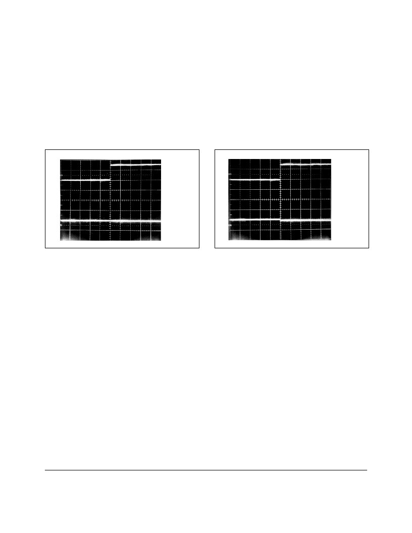
The waveforms in Figure 4 confirm that a test board built
with the zero profile pin connectors shows no evidence of
signal coupling from the digital control pin to the inverting
input. The board layout uses the technique mentioned earlier
of routing a minimum width feedback trace underneath the
circuit. In this example, the socket is empty and the signals
are measured just as they were in Figure 2.
Figure 5 demonstrates the reward for the attention to detail
covered by this discussion. The pedestal is a barely percep-
tible –0.5mV for the same unity gain configuration and for
the same unit as illustrated in Figure 3.
FIGURE 4. Signal Coupling from Pin 14 to Pin 1 for Empty
Zero Profile Socket.
FIGURE 5. Pedestal Error Resulting from the Use of a Zero
Profile Socket.
–Input
5mV/div
0V
S/H Input
2V/div
0V
100
μ
s/div
100
μ
s/div
V
5mV/div
0V
S/H Input
2V/div
0V
The information provided herein is believed to be reliable; however, BURR-BROWN assumes no responsibility for inaccuracies or omissions. BURR-BROWN assumes
no responsibility for the use of this information, and all use of such information shall be entirely at the user’s own risk. Prices and specifications are subject to change
without notice. No patent rights or licenses to any of the circuits described herein are implied or granted to any third party. BURR-BROWN does not authorize or warrant
any BURR-BROWN product for use in life support devices and/or systems.
相关PDF资料 |
PDF描述 |
|---|---|
| AB-070 | AB-070 - Complete Temperature Data Acquisition System from a Single +5V Supply |
| AB-071 | AB-071 - Design a 60Hz Notch Filter with the UAF42 |
| AB-072 | AB-072 - DYNAMIC TESTS FOR A/D CONVERTER PERFORMANCE |
| AB-075 | AB-075 - PHOTODIODE MONITORING WITH OP AMPS |
| AB-076 | AB-076 - Noise Analysis of FET Transimpedance Amplifiers |
相关代理商/技术参数 |
参数描述 |
|---|---|
| AB-070 | 制造商:未知厂家 制造商全称:未知厂家 功能描述:AB-070 - Complete Temperature Data Acquisition System from a Single +5V Supply |
| AB-071 | 制造商:未知厂家 制造商全称:未知厂家 功能描述:AB-071 - Design a 60Hz Notch Filter with the UAF42 |
| AB-072 | 制造商:未知厂家 制造商全称:未知厂家 功能描述:AB-072 - DYNAMIC TESTS FOR A/D CONVERTER PERFORMANCE |
| AB-075 | 制造商:未知厂家 制造商全称:未知厂家 功能描述:AB-075 - PHOTODIODE MONITORING WITH OP AMPS |
| AB-0751BA-01WA-P30-S | 制造商:A-BRIGHT 制造商全称:A-BRIGHT Inc 功能描述:HIGH POWER LED BULB |
发布紧急采购,3分钟左右您将得到回复。