- 您现在的位置:买卖IC网 > PDF目录9379 > AD5112BCPZ5-500R7 (Analog Devices Inc)IC DGTL POT 64POS 5K 8LFCSP PDF资料下载
参数资料
| 型号: | AD5112BCPZ5-500R7 |
| 厂商: | Analog Devices Inc |
| 文件页数: | 18/28页 |
| 文件大小: | 0K |
| 描述: | IC DGTL POT 64POS 5K 8LFCSP |
| 标准包装: | 1 |
| 接片: | 64 |
| 电阻(欧姆): | 5k |
| 电路数: | 1 |
| 温度系数: | 标准值 35 ppm/°C |
| 存储器类型: | 非易失 |
| 接口: | I²C,2 线串口 |
| 电源电压: | 1.8 V ~ 5 V,2.3 V ~ 5.5V |
| 工作温度: | -40°C ~ 125°C |
| 安装类型: | 表面贴装 |
| 封装/外壳: | 8-UFDFN 裸露焊盘,CSP |
| 供应商设备封装: | 8-LFCSP-UD(2x2) |
| 包装: | 标准包装 |
| 其它名称: | AD5112BCPZ5-500R7DKR |
第1页第2页第3页第4页第5页第6页第7页第8页第9页第10页第11页第12页第13页第14页第15页第16页第17页当前第18页第19页第20页第21页第22页第23页第24页第25页第26页第27页第28页
Data Sheet
AD5110/AD5112/AD5114
Rev. B | Page 25 of 28
Similar to the mechanical potentiometer, the resistance of
the RDAC between the W terminal and the A terminal also
produces a digitally controlled complementary resistance, RWA.
RWA also gives a maximum of 8% absolute resistance error. RWA
starts at the maximum resistance value and decreases as the
data loaded into the latch increases. The general equations for
this operation are
W
AB
AW
R
+
=
Bottom scale (0xFF) (7)
W
AB
AW
R
D
R
+
×
=
128
)
(
From 0x00 to 0x7F (8)
TS
AW
R
=
Top scale (0x80) (9)
W
AB
AW
R
+
=
Bottom scale (0xFF) (10)
W
AB
AW
R
D
R
+
×
=
64
)
(
From 0x00 to 0x3F (11)
TS
AW
R
=
Top scale (0x40) (12)
W
AB
AW
R
+
=
Bottom scale (0xFF) (13)
W
AB
AW
R
D
R
+
×
=
32
)
(
From 0x00 to 0x1F (14)
TS
AW
R
=
Top scale (0x20) (15)
where:
D is the decimal equivalent of the binary code in the 5-/6-/7-bit
RDAC register.
RAB is the end-to-end resistance.
RW is the wiper resistance.
RTS is the wiper resistance at top scale.
In the bottom-scale condition or top-scale condition, a finite
total wiper resistance of 45 Ω is present. Regardless of which
setting the part is operating in, take care to limit the current
between Terminal A to Terminal B, Terminal W to Terminal A,
and Terminal W to Terminal B, to the maximum continuous
current of ±6 mA or to the pulse current specified in Table 6.
Otherwise, degradation or possible destruction of the internal
switch contact can occur.
Calculating the Actual End-to-End Resistance
The resistance tolerance is stored in the internal memory
during factory testing. The actual end-to-end resistance can,
therefore, be calculated, which is valuable for calibration,
tolerance matching, and precision applications.
The resistance tolerance in percentage is stored in fixed-point
format, using an 8-bit sign magnitude binary. The data can be
read back by executing Command 6 and setting Bit DB0 (A0).
The MSB is the sign bit (0 = and 1 = +) and the next four bits
are the integer part, the fractional part is represented by the
three LSBs, as shown in Table 11.
Table 11. Tolerance Format
Data Byte
DB7
DB6
DB5
DB4
DB3
DB2
DB1
DB0
Sign
24
23
22
21
.
2-1
2-2
2-3
For example, if RAB = 10 k and the data readback shows
01010010, the end-to-end resistance can be calculated as,
if,
DB[7] is 0 = negative
DB[6:3] is 1010 = 10
DB[2:0] is 010 = 2 × 23 = 0.25
then,
tolerance = 10.25% and, therefore, RAB = 8.975 k
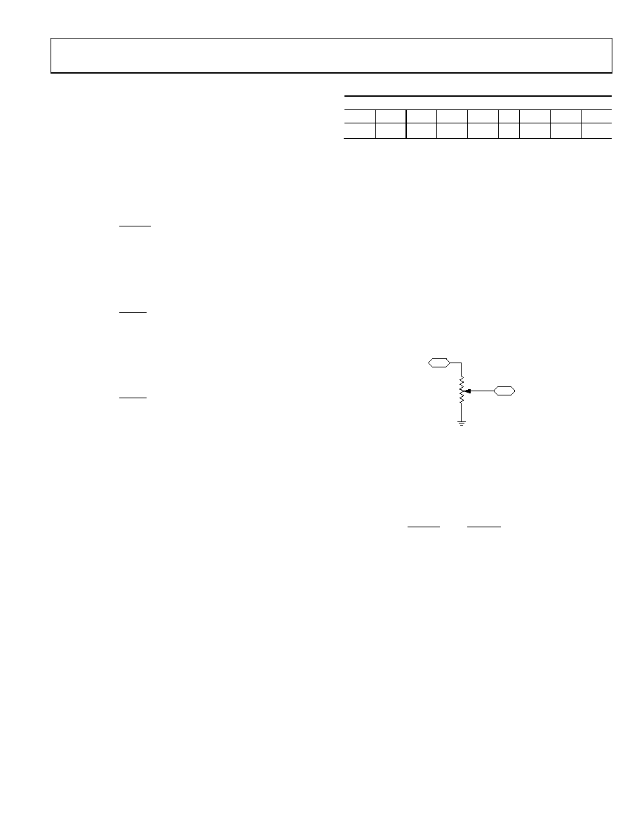
PROGRAMMING THE POTENTIOMETER DIVIDER
Voltage Output Operation
The digital potentiometer easily generates a voltage divider at
wiper-to-B and wiper-to-A that is proportional to the input
voltage at A to B, as shown in Figure 48. Unlike the polarity of
VDD to GND, which must be positive, voltage across A-to-B, W-
to-A, and W-to-B can be at either polarity.
A
VI
W
B
VO
09582-
048
Figure 48. Potentiometer Mode Configuration
Connecting Terminal A to 5 V and Terminal B to ground
produces an output voltage at the Wiper W to Terminal B
ranging from 0 V to 5 V. The general equation defining the
output voltage at VW with respect to ground for any valid input
voltage applied to Terminal A and Terminal B, is:
B
AB
AW
A
AB
WB
W
V
R
D
R
V
R
D
R
D
V
×
+
×
=
)
(
)
(
)
(
(16)
where:
RWB(D) can be obtained from Equation 1 to Equation 6.
RAW(D) can be obtained from Equation 7 to Equation 15.
Operation of the digital potentiometer in the divider mode
results in a more accurate operation over temperature. Unlike
the rheostat mode, the output voltage is dependent mainly on
the ratio of the internal resistors, RAW and RWB, and not the
absolute values. Therefore, the temperature drift reduces to
5 ppm/°C.
相关PDF资料 |
PDF描述 |
|---|---|
| ISL12029IB27Z-T | IC RTC EEPROM LP 2.63V 14-SOIC |
| VI-2NN-MX-B1 | CONVERTER MOD DC/DC 18.5V 75W |
| VI-2NN-MW | CONVERTER MOD DC/DC 18.5V 100W |
| ISL12029IBZ-T | IC RTC EEPROM LP 4.38V 14-SOIC |
| VI-2NM-MX-B1 | CONVERTER MOD DC/DC 10V 75W |
相关代理商/技术参数 |
参数描述 |
|---|---|
| AD5112BCPZ5-RL7 | 功能描述:IC DGTL POT 64POS 5K SGL 8LFCSP RoHS:是 类别:集成电路 (IC) >> 数据采集 - 数字电位器 系列:- 标准包装:3,000 系列:DPP 接片:32 电阻(欧姆):10k 电路数:1 温度系数:标准值 300 ppm/°C 存储器类型:非易失 接口:3 线串行(芯片选择,递增,增/减) 电源电压:2.5 V ~ 6 V 工作温度:-40°C ~ 85°C 安装类型:表面贴装 封装/外壳:8-WFDFN 裸露焊盘 供应商设备封装:8-TDFN(2x3) 包装:带卷 (TR) |
| AD5112BCPZ80-1-RL7 | 功能描述:IC DGTL POT 64POS 80K SGL 8LFCSP RoHS:是 类别:集成电路 (IC) >> 数据采集 - 数字电位器 系列:- 标准包装:3,000 系列:DPP 接片:32 电阻(欧姆):10k 电路数:1 温度系数:标准值 300 ppm/°C 存储器类型:非易失 接口:3 线串行(芯片选择,递增,增/减) 电源电压:2.5 V ~ 6 V 工作温度:-40°C ~ 85°C 安装类型:表面贴装 封装/外壳:8-WFDFN 裸露焊盘 供应商设备封装:8-TDFN(2x3) 包装:带卷 (TR) |
| AD5112BCPZ80-500R7 | 功能描述:IC DGTL POT 64POS 80K 8LFCSP RoHS:是 类别:集成电路 (IC) >> 数据采集 - 数字电位器 系列:- 标准包装:3,300 系列:WiperLock™ 接片:257 电阻(欧姆):100k 电路数:1 温度系数:标准值 150 ppm/°C 存储器类型:易失 接口:3 线 SPI(芯片选择) 电源电压:1.8 V ~ 5.5 V 工作温度:-40°C ~ 125°C 安装类型:表面贴装 封装/外壳:8-VDFN 裸露焊盘 供应商设备封装:8-DFN-EP(3x3) 包装:带卷 (TR) |
| AD5112BCPZ80-RL7 | 功能描述:IC DGTL POT 64POS 80K SGL 8LFCSP RoHS:是 类别:集成电路 (IC) >> 数据采集 - 数字电位器 系列:- 标准包装:3,000 系列:DPP 接片:32 电阻(欧姆):10k 电路数:1 温度系数:标准值 300 ppm/°C 存储器类型:非易失 接口:3 线串行(芯片选择,递增,增/减) 电源电压:2.5 V ~ 6 V 工作温度:-40°C ~ 85°C 安装类型:表面贴装 封装/外壳:8-WFDFN 裸露焊盘 供应商设备封装:8-TDFN(2x3) 包装:带卷 (TR) |
| AD5113 | 制造商:AD 制造商全称:Analog Devices 功能描述:Single-Channel, 128-/64-/32-Position, Up/Down, ±8% Resistor Tolerance, Nonvolatile Digital Potentiometer |
发布紧急采购,3分钟左右您将得到回复。