- 您现在的位置:买卖IC网 > PDF目录9287 > AD5233BRUZ50-R7 (Analog Devices Inc)IC DGTL POT QUAD 64POS 24-TSSOP PDF资料下载
参数资料
| 型号: | AD5233BRUZ50-R7 |
| 厂商: | Analog Devices Inc |
| 文件页数: | 11/32页 |
| 文件大小: | 0K |
| 描述: | IC DGTL POT QUAD 64POS 24-TSSOP |
| 标准包装: | 1,000 |
| 接片: | 64 |
| 电阻(欧姆): | 50k |
| 电路数: | 4 |
| 温度系数: | 标准值 600 ppm/°C |
| 存储器类型: | 非易失 |
| 接口: | 4 线 SPI(芯片选择) |
| 电源电压: | 2.7 V ~ 5.5 V,±2.25 V ~ 2.75 V |
| 工作温度: | -40°C ~ 85°C |
| 安装类型: | 表面贴装 |
| 封装/外壳: | 24-TSSOP(0.173",4.40mm 宽) |
| 供应商设备封装: | 24-TSSOP |
| 包装: | 带卷 (TR) |
第1页第2页第3页第4页第5页第6页第7页第8页第9页第10页当前第11页第12页第13页第14页第15页第16页第17页第18页第19页第20页第21页第22页第23页第24页第25页第26页第27页第28页第29页第30页第31页第32页
AD5233
Rev. B | Page 19 of 32
ADVANCED CONTROL MODES
The AD5233 digital potentiometer includes a set of user
programming features to address the wide number of
applications for these universal adjustment devices.
Key programming features include
Scratchpad programming to any desirable values
Nonvolatile memory storage of the scratchpad RDAC
register value in the EEMEM register
Increment and decrement instructions for the RDAC
wiper register
Left- and right-bit shift of the RDAC wiper register to
achieve ±6 dB level changes
Eleven extra bytes of user-addressable nonvolatile memory
Linear Increment and Decrement Instructions
The increment and decrement instructions (14, 15, 6, and 7)
are useful for linear step-adjustment applications. These com-
mands simplify microcontroller software coding by allowing the
controller to send just an increment or decrement command to
the device.
For an increment command, executing Instruction 14 with
the proper address automatically moves the wiper to the next
resistance segment position. Instruction 15 performs the same
function, except that the address does not need to be specified.
All RDACs are changed at the same time.
Logarithmic Taper Mode Adjustment
Four programming instructions produce logarithmic taper
increment and decrement of the wiper. These settings are
activated by the 6 dB increment and 6 dB decrement instruc-
tions (12, 13, 4, and 5). For example, starting at zero scale,
executing the increment Instruction 12 seven times moves
the wiper in 6 dB per step from 0% to full scale, RAB. The 6 dB
increment instruction doubles the value of the RDAC register
contents each time the command is executed. When the wiper
position is near the maximum setting, the last 6 dB increment
instruction causes the wiper to go to the full-scale 6310 code
position. Further 6 dB per increment instructions do not
change the wiper position beyond its full scale.
The 6 dB step increments and 6 dB step decrements are achieved
by shifting the bit internally to the left or right, respectively.
The following information explains the nonideal ±6 dB step
adjustment under certain conditions. Table 8 illustrates the
operation of the shifting function on the RDAC register data
bits. Each table row represents a successive shift operation.
Note that the left-shift 12 and 13 instructions were modified
such that, if the data in the RDAC register is equal to zero and
the data is shifted left, the RDAC register is then set to Code 1.
Similarly, if the data in the RDAC register is greater than or
equal to midscale and the data is shifted left, then the
data in the RDAC register is automatically set to full scale. This
makes the left-shift function as ideal a logarithmic adjustment
as possible.
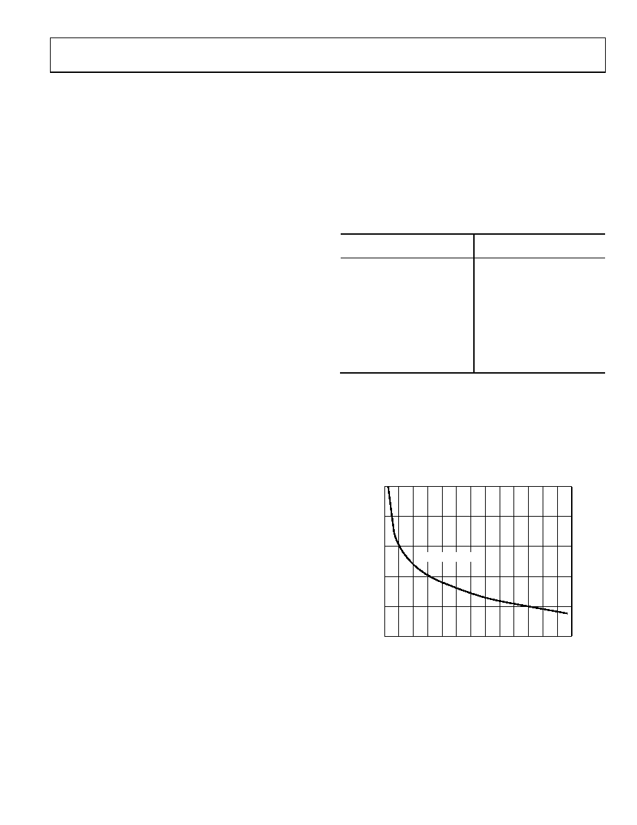
The right-shift 4 and 5 instructions are ideal only if the LSB is
0 (ideal logarithmic = no error). If the LSB is a 1, the right-shift
function generates a linear half-LSB error, which translates to
a number-of-bits-dependent logarithmic error, as shown in
Figure 42. The plot shows the error of the odd numbers of bits
for the AD5233.
Table 8. Detail Left-Shift and Right-Shift Functions for
6 dB Step Increment and Decrement
Left-Shift
(+6 dB/Step)
Right-Shift
(–6 dB/Step)
00 0000
11 1111
00 0001
01 1111
00 0010
00 1111
00 0100
00 0111
00 1000
00 0011
01 0000
00 0001
10 0000
00 0000
11 1111
00 0000
11 1111
00 0000
Actual conformance to a logarithmic curve between the data
contents in the RDAC register and the wiper position for each
right-shift 4 and 5 command execution contains an error only
for odd numbers of bits. Even numbers of bits are ideal. The
code)] for the AD5233. For example, Code 3 log error = 20 ×
log10 (0.5/3) = 15.56 dB, which is the worst-case scenario. The
plot of log error is more significant at the lower codes.
CODE (Decimal)
0
E
RRO
R
(
d
B)
–10
–50
–40
–30
–20
–15.56dB @ CODE 3
5
10
152025
30354045 505560
65
02
79
4-
0
43
Figure 42. Plot of Log Error Conformance for Odd Numbers of Bits Only (Even
Numbers of Bits are Ideal)
相关PDF资料 |
PDF描述 |
|---|---|
| VI-B4Z-MX-F1 | CONVERTER MOD DC/DC 2V 30W |
| MS27473T20B2PA | CONN PLUG 65POS STRAIGHT W/PINS |
| VI-B4Z-MW-F4 | CONVERTER MOD DC/DC 2V 40W |
| AD5233BRUZ100-R7 | IC DGTL POT QUAD 64POS 24-TSSOP |
| DS1100LZ-20+T | IC DELAY LINE 5TAP 20NS 8-SOIC |
相关代理商/技术参数 |
参数描述 |
|---|---|
| AD5235 | 制造商:AD 制造商全称:Analog Devices 功能描述:8-Bit Dual Nonvolatile Memory Digital Potentiometer |
| AD5235BRU25 | 制造商:Analog Devices 功能描述:Digital Potentiometer 1024POS 25KOhm Dual 16-Pin TSSOP 制造商:Analog Devices 功能描述:IC DIGITAL POT 25KOHM 1024 DUAL 16-TSSO |
| AD5235BRU250 | 制造商:Analog Devices 功能描述:Digital Potentiometer 1024POS 250KOhm Dual 16-Pin TSSOP 制造商:Analog Devices 功能描述:IC DUAL DIGITAL POT. 10-BIT |
| AD5235BRU250-RL7 | 制造商:Analog Devices 功能描述:DGTL POTENTIOMETER 1024POS 250KOHM DUAL 16TSSOP - Tape and Reel |
| AD5235BRU25-EP-RL7 | 制造商:Analog Devices 功能描述:Digital Potentiometer 1024POS 25KOhm Dual 16-Pin TSSOP T/R 制造商:Analog Devices 功能描述:DUAL 10-BIT SPI DIG. POT - Tape and Reel 制造商:Analog Devices 功能描述:IC DGTL POT 1024POS DUAL 16TSSOP 制造商:Analog Devices Inc. 功能描述:Digital Potentiometer ICs IC Dual 10-Bit SPI |
发布紧急采购,3分钟左右您将得到回复。