- 您现在的位置:买卖IC网 > PDF目录22159 > AD654JRZ-REEL (Analog Devices Inc)IC V-F CONVERTER MONO 8-SOIC TR PDF资料下载
参数资料
| 型号: | AD654JRZ-REEL |
| 厂商: | Analog Devices Inc |
| 文件页数: | 8/12页 |
| 文件大小: | 354K |
| 描述: | IC V-F CONVERTER MONO 8-SOIC TR |
| 标准包装: | 2,500 |
| 类型: | 电压至频率 |
| 频率 - 最大: | 500kHz |
| 全量程: | ±50ppm/°C |
| 线性: | ±0.2% |
| 安装类型: | 表面贴装 |
| 封装/外壳: | 8-SOIC(0.154",3.90mm 宽) |
| 供应商设备封装: | 8-SOIC |
| 包装: | 带卷 (TR) |
AD654
8
REV.
At the receiver side, the output transistor is operated in the
photo-transistor mode; that is with the base lead (Pin 6) open.
This allows the highest possible output current. For reasonable
speed in this mode, it is imperative that the load impedance be
as low as possible. This is provided by the single transistor stage
current-to-voltage converter, which has a dynamic load imped-
ance of less than 10 ohms and interfaces with TTL at the output.
USING A STAND-ALONE FREQUENCY COUNTER/LED
DISPLAY DRIVER FOR VOLTMETER APPLICATIONS
Figure 10 shows the AD654 used with a stand-alone frequency
counter/LED display driver. With C
T
= 1000 pF and R
T
= 1 k&
the AD654 produces an FS frequency of 100 kHz when V
IN
=
+1 V. This signal is fed into the ICM7226A, a universal counter
system that drives common anode LEDs. With the FUNCTION
pin tied to D1 through a 10 k& resistor the ICM7226A counts the
frequency of the signal at A
IN
. This count period is selected by
the user and can be 10 ms, 100 ms, 1s, or 10 seconds, as shown on
Pin 21. The longer the period selected, the more resolution the
count will have. The ICM7226A then displays the frequency on
the LEDs, driving them directly as shown. Refreshing of the LEDs
is handled automatically by the ICM7226. The entire circuit op-
erates on a single +5 V supply and gives a meter with 3, 4, or 5
digit resolution.
40
39
38
37
36
35
34
33
32
31
30
29
28
27
26
25
24
23
22
21
1
2
3
4
5
6
7
8
9
10
11
12
13
14
15
16
17
18
19
20
8
7
6
5
1
2
3
4
V
IN
(0V TO 1V)
5V
5V
1k
1000pF
500 825
1k
AD654
DI PIN 30
10k
30k
5V
5V
10MHz
CRYSTAL
22M
39pF
39pF
5V
5V
10k
5V
D1 (10ms)
D2 (100ms)
D3 (1s)
D4 (10s)
4
8
8
D.P. g
e d c b a
f
LED
OVERFLOW
INDICATOR
D8 D7 D6 D5 D4 D3 D2 D1
AIN
HOLD
NC
OSL JN
OSL OUT
NC
D1
D2
D3
D4
D5
V+
D6
D7
D8
RANGE
ICM7226A
FUNCTION
dp
e
g
a
GND
d
b
c
f
+
N = N NNE T
Figure 10. AD654 With Stand-Alone Frequency Counter/
LED Display Driver
Longer count periods not only result in the count having more
resolution, they also serve as an integration of noisy analog signals.
For example, a normal-mode 60 Hz sine wave riding on the input
of the AD654 will result in the output frequency increasing on
the positive half of the sine wave and decreasing on the negative
half of the sine wave. This effect is cancelled by selecting a count
period equal to an integral number of noise signal periods. A
100 ms count period is effective because it not only has an inte-
gral number of 60 Hz cycles (6), it also has an integral number
of 50 Hz cycles (5). This is also true of the 1 second and 10 sec-
ond count period.
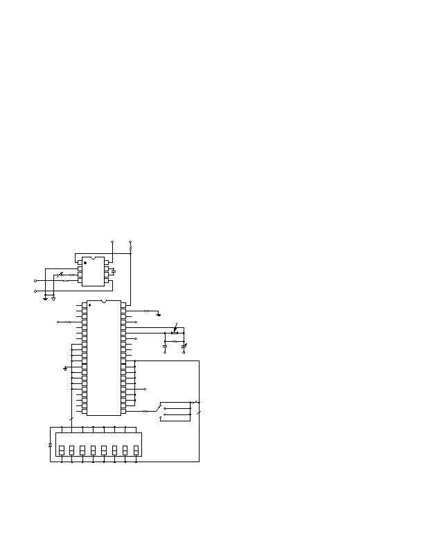
AD654-BASED ANALOG-TO-DIGITAL CONVERSION
USING A SINGLE CHIP MICROCOMPUTER
The AD654 can serve as an analog-to-digital converter when
used with a single component microcomputer that has an inter-
val timer/event counter such as the 8048. Figure 11 shows the
AD654, with a full-scale input voltage of +1 V and a full-scale
output frequency of 100 kHz, connected to the timer/counter
input Pin T1 of the 8048. Such a system can also operate on a
single +5 V supply.
The 8748 counter is negative edge triggered; after the STRT
CNT instruction is executed subsequent high to low transitions
on T1 increment the counter. The maximum rate at which the
counter may be incremented is once per three instruction cycles;
using a 6 MHz crystal, this corresponds to once every 7.5 祍, or
a maximum frequency of 133 kHz. Because the counter overflows
every 256 counts (8 bits), the timer interrupt is enabled. Each
overflow then causes a jump to a subroutine where a register is
incremented. After the STOP TCNT instruction is executed, the
number of overflows that have occurred will be the number in
this register. The number in this register multiplied by 256 plus
the number in the counter will be the total number of negative
edges counted during the count period. The count period is
handled simply by decrementing a register the number of times
necessary to correspond to the desired count time. After the
register has been decremented the required number of times the
STOP TCNT instruction is executed.
The total number of negative edges counted during the count
period is proportional to the input voltage. For example, if a 1 V
full-scale input voltage produces a 100 kHz signal and the count
period is 100 ms, then the total count will be 10,000. Scaling
from this maximum is then used to determine the input voltage,
i.e., a count of 5000 corresponds to an input voltage of 0.5 V.
As with the ICM7226, longer count times result in counts hav-
ing more resolution; and they result in the integration of noisy
analog signals.
相关PDF资料 |
PDF描述 |
|---|---|
| IDT7164S35YG | IC SRAM 64KBIT 35NS 28SOJ |
| AD7741BR | IC CONVERTER V TO FREQ 8-SOIC |
| IDT7164S35TPG | IC SRAM 64KBIT 35NS 28DIP |
| AD7741YR-REEL7 | IC CONVERTER V TO FREQ 8-SOIC |
| IDT7164S20YI8 | IC SRAM 64KBIT 20NS 28SOJ |
相关代理商/技术参数 |
参数描述 |
|---|---|
| AD654JRZ-REEL7 | 功能描述:IC V-F CONVERTER MONO 8-SOIC TR RoHS:是 类别:集成电路 (IC) >> PMIC - V/F 和 F/V 转换器 系列:- 标准包装:1 系列:- 类型:频率至电压 频率 - 最大:10kHz 全量程:- 线性:±0.3% 安装类型:表面贴装 封装/外壳:8-SOIC(0.154",3.90mm 宽) 供应商设备封装:8-SOIC 包装:Digi-Reel® 其它名称:LM2917MX-8/NOPBDKR |
| AD6555XBC | 制造商:Analog Devices 功能描述:QUAD-BAND GSM/EDGE X-PA POWER AMPLIFIER - Trays |
| AD660 | 制造商:AD 制造商全称:Analog Devices 功能描述:Monolithic 16-Bit Serial/Byte DACPORT |
| AD660_08 | 制造商:AD 制造商全称:Analog Devices 功能描述:Monolithic 16-Bit Serial/Byte DACPORT |
| AD6600 | 制造商:AD 制造商全称:Analog Devices 功能描述:Dual Channel, Gain-Ranging ADC with RSSI |
发布紧急采购,3分钟左右您将得到回复。