- 您现在的位置:买卖IC网 > PDF目录10756 > AD73311ARZ (Analog Devices Inc)IC PROCESSOR FRONT END LP 20SOIC PDF资料下载
参数资料
| 型号: | AD73311ARZ |
| 厂商: | Analog Devices Inc |
| 文件页数: | 8/36页 |
| 文件大小: | 0K |
| 描述: | IC PROCESSOR FRONT END LP 20SOIC |
| 标准包装: | 37 |
| 位数: | 16 |
| 通道数: | 2 |
| 功率(瓦特): | 50mW |
| 电压 - 电源,模拟: | 3V |
| 电压 - 电源,数字: | 3V |
| 封装/外壳: | 20-SOIC(0.295",7.50mm 宽) |
| 供应商设备封装: | 20-SOIC W |
| 包装: | 管件 |
| 产品目录页面: | 799 (CN2011-ZH PDF) |
第1页第2页第3页第4页第5页第6页第7页当前第8页第9页第10页第11页第12页第13页第14页第15页第16页第17页第18页第19页第20页第21页第22页第23页第24页第25页第26页第27页第28页第29页第30页第31页第32页第33页第34页第35页第36页
AD73311
–16–
REV. B
OPERATION
Resetting the AD73311
The pin
RESET resets all the control registers. All registers
are reset to zero indicating that the default SCLK rate
(DMCLK/8) and sample rate (DMCLK/2048) are at a mini-
mum to ensure that slow speed DSP engines can communicate
effectively. As well as resetting the control registers using the
RESET pin, the device can be reset using the RESET bit (CRA:7)
in Control Register A. Both hardware and software resets re-
quire 4 DMCLK cycles. On reset, DATA/
PGM (CRA:0) is set
to 0 (default condition) thus enabling Program Mode. The reset
conditions ensure that the device must be programmed to the
correct settings after power-up or reset. Following a reset, the
SDOFS will be asserted 280 DMCLK cycles after
RESET
going high. The data that is output following
RESET and dur-
ing Program Mode is random and contains no valid information
until either data or mixed mode is set.
Power Management
The individual functional blocks of the AD73311 can be en-
abled separately by programming the power control register
CRC. It allows certain sections to be powered down if not re-
quired, which adds to the device’s flexibility in that the user
need not incur the penalty of having to provide power for a
certain section if it is not necessary to their design. The power
control register provides individual control settings for the major
functional blocks and also a global override that allows all sec-
tions to be powered up by setting the bit. Using this method the
user could, for example, individually enable a certain section,
such as the reference (CRC:5), and disable all others. The glo-
bal power-up (CRC:0) can be used to enable all sections but if
power-down is required using the global control, the reference
will still be enabled, in this case, because its individual bit is set.
Refer to Table XIII for details of the settings of CRC.
Operating Modes
There are five operating modes available on the AD73311. Two
of these—Analog Loop-Back and Digital Loop-Back—are
reserved as diagnostic modes with the other three, Program,
Data and Mixed Program/Data, being available for general
purpose use. The device configuration—register settings—can
be changed only in Program and Mixed Program/Data Modes.
In all modes, transfers of information to or from the device
occur in 16-bit packets, therefore the DSP engine’s SPORT
will be programmed for 16-bit transfers.
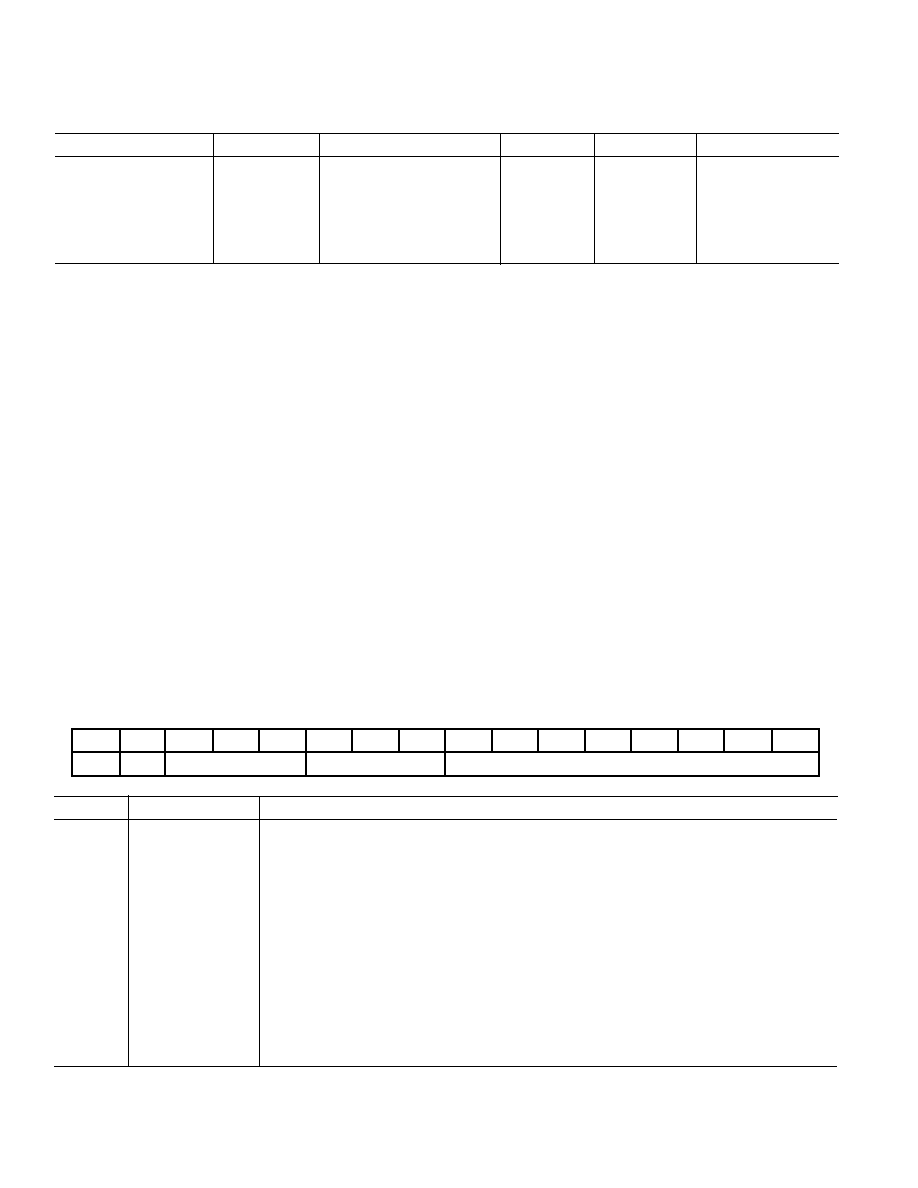
Table X. Control Word Description
15
14
13
12
11
10
9
8
7
6
5
4
3
2
1
0
C/
D
R/
W
DEVICE ADDRESS
REGISTER ADDRESS
REGISTER DATA
Control
Frame
Description
Bit 15
Control/
Data
When set high, it signifies a control word in Program or Mixed Program/Data Modes. When
set low, it signifies a data word in Mixed Program/Data Mode or an invalid control word in
Program Mode.
Bit 14
Read/
Write
When set low, it tells the device that the data field is to be written to the register selected by
the register field setting provided the address field is zero. When set high, it tells the device
that the selected register is to be written to the data field in the input serial register and that
the new control word is to be output from the device via the serial output.
Bits 13–11
Device Address
This 3-bit field holds the address information. Only when this field is zero is a device se-
lected. If the address is not zero, it is decremented and the control word is passed out of
the device via the serial output.
Bits 10–8
Register Address
This 3-bit field is used to select one of the five control registers on the AD73311.
Bits 7–0
Register Data
This 8-bit field holds the data that is to be written to or read from the selected register
provided the address field is zero.
Table IX. Control Register Map
Address (Binary)
Name
Description
Type
Width
Reset Setting (Hex)
000
CRA
Control Register A
R/W
8
0x00
001
CRB
Control Register B
R/W
8
0x00
010
CRC
Control Register C
R/W
8
0x00
011
CRD
Control Register D
R/W
8
0x00
100
CRE
Control Register E
R/W
8
0x00
101 to 111
Reserved
相关PDF资料 |
PDF描述 |
|---|---|
| VE-J5F-MW-F1 | CONVERTER MOD DC/DC 72V 100W |
| VI-B6V-IV-S | CONVERTER MOD DC/DC 5.8V 150W |
| AD73311LARSZ-REEL7 | IC PROCESSOR FRONT END LP 20SSOP |
| MAX9031AXK+T | IC COMPARATOR SGL SC70-5 |
| VE-J5D-MW-F4 | CONVERTER MOD DC/DC 85V 100W |
相关代理商/技术参数 |
参数描述 |
|---|---|
| AD73311ARZ-REEL | 功能描述:IC PROCESSOR FRONT END LP 20SOIC RoHS:是 类别:集成电路 (IC) >> 数据采集 - 模拟前端 (AFE) 系列:- 产品培训模块:Lead (SnPb) Finish for COTS Obsolescence Mitigation Program 标准包装:2,500 系列:- 位数:- 通道数:2 功率(瓦特):- 电压 - 电源,模拟:3 V ~ 3.6 V 电压 - 电源,数字:3 V ~ 3.6 V 封装/外壳:32-VFQFN 裸露焊盘 供应商设备封装:32-QFN(5x5) 包装:带卷 (TR) |
| AD73311L | 制造商:AD 制造商全称:Analog Devices 功能描述:Low Cost, Low Power CMOS General Purpose Analog Front End |
| AD73311LAR | 制造商:Analog Devices 功能描述:Audio Codec 1ADC / 1DAC 16-Bit 20-Pin SOIC W 制造商:Rochester Electronics LLC 功能描述:SINGLE-CHANNEL AFE I.C. - Bulk |
| AD73311LAR-REEL | 制造商:Analog Devices 功能描述:Audio Codec 1ADC / 1DAC 16-Bit 20-Pin SOIC W T/R 制造商:Rochester Electronics LLC 功能描述:SINGLE-CHANNEL AFE I.C. - Tape and Reel |
| AD73311LAR-REEL7 | 制造商:Analog Devices 功能描述:Audio Codec 1ADC / 1DAC 16-Bit 20-Pin SOIC W T/R 制造商:Rochester Electronics LLC 功能描述:SINGLE-CHANNEL AFE I.C. - Tape and Reel |
发布紧急采购,3分钟左右您将得到回复。