- 您现在的位置:买卖IC网 > PDF目录10745 > AD73360LARZ (Analog Devices Inc)IC PROCESSOR FRONTEND 6CH 28SOIC PDF资料下载
参数资料
| 型号: | AD73360LARZ |
| 厂商: | Analog Devices Inc |
| 文件页数: | 16/35页 |
| 文件大小: | 0K |
| 描述: | IC PROCESSOR FRONTEND 6CH 28SOIC |
| 标准包装: | 27 |
| 位数: | 16 |
| 通道数: | 6 |
| 功率(瓦特): | 80mW |
| 电压 - 电源,模拟: | 3V |
| 电压 - 电源,数字: | 3V |
| 封装/外壳: | 28-SOIC(0.295",7.50mm 宽) |
| 供应商设备封装: | 28-SOIC W |
| 包装: | 管件 |
第1页第2页第3页第4页第5页第6页第7页第8页第9页第10页第11页第12页第13页第14页第15页当前第16页第17页第18页第19页第20页第21页第22页第23页第24页第25页第26页第27页第28页第29页第30页第31页第32页第33页第34页第35页
REV. A
AD73360
–23–
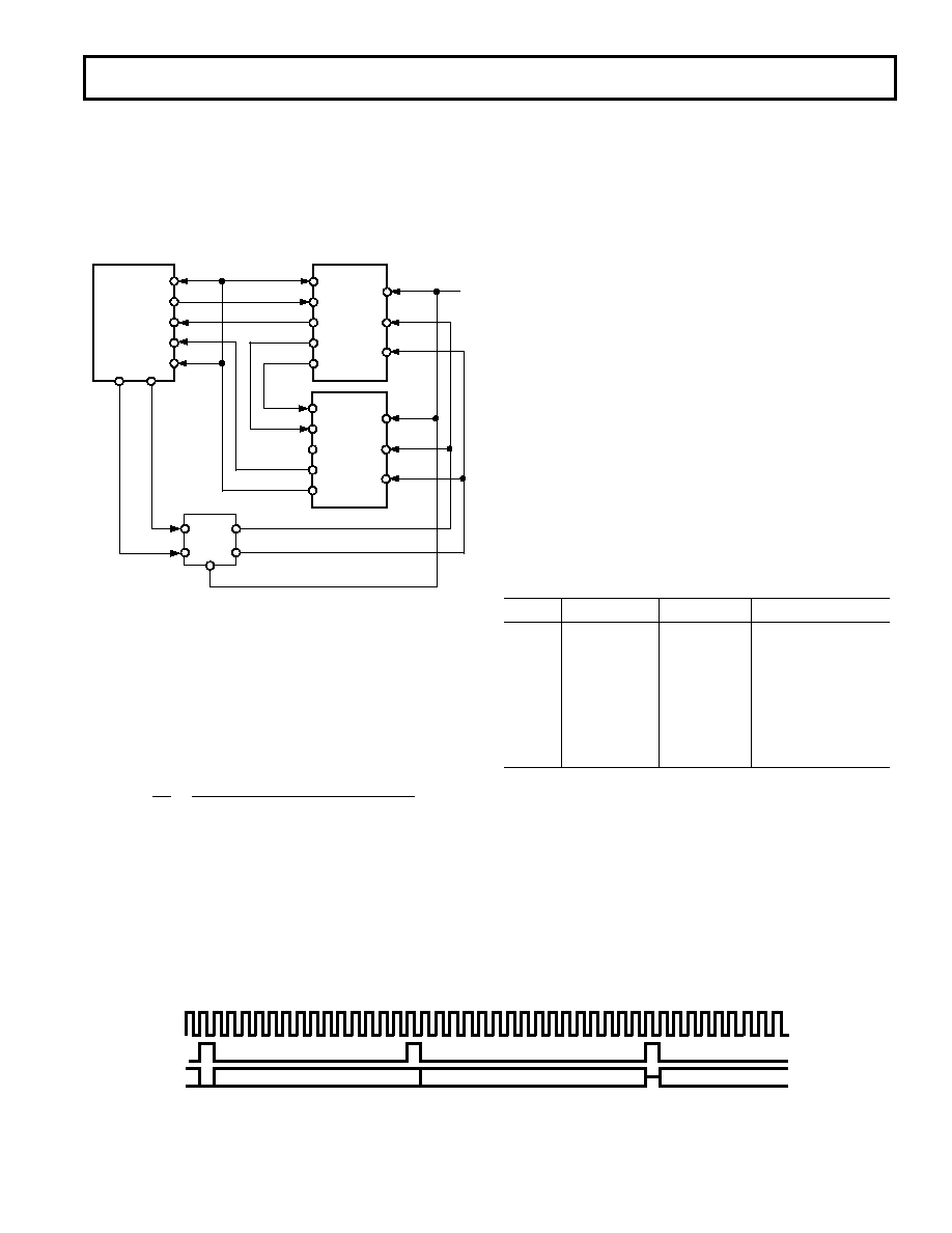
Cascade Operation
The AD73360 has been designed to support up to eight devices
in a cascade connected to a single serial port (see Figure 17).
The SPORT interface protocol has been designed so that device
addressing is built into the packet of information sent to the
device. This allows the cascade to be formed with no extra hard-
ware overhead for control signals or addressing. A cascade can
be formed in either of the two modes previously discussed.
TFS
DT
DR
RFS
AD73360
SDIFS
SDI
SCLK
SDO
SDOFS
SCLK
DEVICE 1
MCLK
SE
RESET
AD73360
74HC74
Q0
Q1
D1
D0
FL0
FL1
ADSP-2181
DSP
CLK
SDIFS
SDI
SCLK
SDO
SDOFS
DEVICE 2
MCLK
SE
RESET
Figure 17. Connection of Two AD73360s Cascaded to
ADSP-2181
There may be some restrictions in cascade operation due to the
number of devices configured in the cascade and the serial clock
rate chosen. The formula below gives an indication of whether
the combination of sample rate, serial clock and number of
devices can be successfully cascaded. This assumes a directly
coupled frame sync arrangement as shown in Figure 12 and does
not take any interrupt latency into account.
16
1
16
17
f
Device Count
SCLK
S
≥
× ×
+
[((
)
]
When using the indirectly coupled frame sync configuration in
cascaded operation it is necessary to be aware of the restrictions
in sending control word data to all devices in the cascade. The
user should ensure that there is sufficient time for all the control
words to be sent between reading the last ADC sample and the
start of the next sample period.
In Cascade Mode, each device must know the number of de-
vices in the cascade to be able to output data at the correct
time. Control Register A contains a 3-bit field (DC0–2) that is
programmed by the DSP during the programming phase. The
default condition is that the field contains 000b, which is equiva-
lent to a single device in cascade (see Table XVIII). However,
for cascade operation this field must contain a binary value that
is one less than the number of devices in the cascade. With a
number of AD73360s in cascade each device takes a turn to
send an ADC result to the DSP. For example, in a cascade of
two devices the data will be output as Device 2-Channel 1,
Device 1-Channel 1, Device 2-Channel 2, Device 1-Channel 2
etc. When the first device in the cascade has transmitted its
channel data there is an additional SCLK period during which
the last device asserts its SDOFS as it begins its transmission of
the next channel. This will not cause a problem for most DSPs
as they count clock edges after a frame sync and hence the
extra bit will be ignored.
When multiple devices are connected in cascade there are also
restrictions concerning which ADC channels can be powered
up. In all cases the cascaded devices must all have the same
channels powered up (i.e., for a cascade of two devices requir-
ing Channels 1 and 2 on Device 1 and Channel 5 on Device 2,
Channels 1, 2 and 5 must be powered up on both devices to
ensure correct operation). Figure 18 shows the timing se-
quence for two devices in cascade.
Table XVIII. Device Count Settings
DC2
DC1
DC0
Cascade Length
00
0
1
00
1
2
01
0
3
01
1
4
10
0
5
10
1
6
11
0
7
11
1
8
Connection of a cascade of devices to a DSP, as shown in
Figure 17, is no more complicated than connecting a single
device. Instead of connecting the SDO and SDOFS to the
DSP’s Rx port, these are now daisy-chained to the SDI and
SDIFS of the next device in the cascade. The SDO and
SDOFS of the final device in the cascade are connected to the
DSP’s Rx port to complete the cascade. SE and
RESET on all
devices are fed from the signals that were synchronized with
the MCLK using the circuit of Figure 19. The SCLK from
only one device need be connected to the DSP’s SCLK input(s)
as all devices will be running at the same SCLK frequency and
phase.
1234 5
6 7
8 910 11 12 13 14 15 16 1234 5
6
7 8 9 10 11 12 13 14 15 16 17
DEVICE 2 - CHANNEL 1
DEVICE 1 - CHANNEL 1
1234 5
6 7
8
DEVICE 2 - CHANNEL 2
Figure 18. Cascade Timing for a Two-Device Cascade
相关PDF资料 |
PDF描述 |
|---|---|
| MAX931ESA+ | IC COMPARATOR W/REF 8-SOIC |
| MAX991EUA+ | IC COMPARATOR R-R 8-UMAX |
| MAX991ESA+ | IC COMPARATOR R-R 8-SOIC |
| MAX992ESA+ | IC COMPARATOR R-R 8-SOIC |
| AD7195BCPZ-RL | IC AFE 24BIT 4.8K 32LFSP |
相关代理商/技术参数 |
参数描述 |
|---|---|
| AD73360LARZ-REEL | 功能描述:IC PROCESSOR FRONTEND 6CH 28SOIC RoHS:是 类别:集成电路 (IC) >> 数据采集 - 模拟前端 (AFE) 系列:- 产品培训模块:Lead (SnPb) Finish for COTS Obsolescence Mitigation Program 标准包装:2,500 系列:- 位数:- 通道数:2 功率(瓦特):- 电压 - 电源,模拟:3 V ~ 3.6 V 电压 - 电源,数字:3 V ~ 3.6 V 封装/外壳:32-VFQFN 裸露焊盘 供应商设备封装:32-QFN(5x5) 包装:带卷 (TR) |
| AD73360LARZ-REEL7 | 功能描述:IC PROCESSOR FRONTEND 6CH 28SOIC RoHS:是 类别:集成电路 (IC) >> 数据采集 - 模拟前端 (AFE) 系列:- 产品培训模块:Lead (SnPb) Finish for COTS Obsolescence Mitigation Program 标准包装:2,500 系列:- 位数:- 通道数:2 功率(瓦特):- 电压 - 电源,模拟:3 V ~ 3.6 V 电压 - 电源,数字:3 V ~ 3.6 V 封装/外壳:32-VFQFN 裸露焊盘 供应商设备封装:32-QFN(5x5) 包装:带卷 (TR) |
| AD7339 | 制造商:AD 制造商全称:Analog Devices 功能描述:5 V Integrated High Speed ADC/Quad DAC System |
| AD7339BS | 制造商:Analog Devices 功能描述:Data Acquisition System Single ADC Quad DAC 8-Bit 52-Pin MQFP |
| AD7339BS-REEL | 制造商:Analog Devices 功能描述:Data Acquisition System Single ADC Quad DAC 8-Bit 52-Pin MQFP T/R |
发布紧急采购,3分钟左右您将得到回复。