- 您现在的位置:买卖IC网 > PDF目录9778 > AD7827BRZ-REEL7 (Analog Devices Inc)IC ADC 8BIT SAMPLING SRL 8SOIC PDF资料下载
参数资料
| 型号: | AD7827BRZ-REEL7 |
| 厂商: | Analog Devices Inc |
| 文件页数: | 11/12页 |
| 文件大小: | 0K |
| 描述: | IC ADC 8BIT SAMPLING SRL 8SOIC |
| 产品变化通告: | AD7827 Series Discontinuation 18/Jul/2012 |
| 标准包装: | 1,000 |
| 位数: | 8 |
| 采样率(每秒): | 1M |
| 数据接口: | DSP,串行 |
| 转换器数目: | 1 |
| 功率耗散(最大): | 30mW |
| 电压电源: | 单电源 |
| 工作温度: | -40°C ~ 105°C |
| 安装类型: | 表面贴装 |
| 封装/外壳: | 8-SOIC(0.154",3.90mm 宽) |
| 供应商设备封装: | 8-SOIC |
| 包装: | 带卷 (TR) |
| 输入数目和类型: | 1 个单端,单极 |
AD7827
–8–
REV. 0
POWER-UP TIMES
The AD7827 has a 1
s power-up time when using an external
reference and a 25
s power-up time when using the on-chip
reference. When VDD is first connected, the AD7827 is in a low
current mode of operation. In order to carry out a conversion
the AD7827 must first be powered up. The AD7827 is pow-
ered up by a rising edge on the
CONVST pin and a conversion
is initiated on the falling edge of
CONVST. Figure 9 shows
how to power up the AD7827 when VDD is first connected or
after the ADC has been powered down using the
CONVST pin
when using either the on-chip, or an external, reference. When
using an external reference the falling edge of
CONVST may
occur before the required power-up time has elapsed; however,
the conversion will not be initiated on the falling edge of
CONVST but rather at the moment when the part has com-
pletely powered up, i.e., after 1
s. If the falling edge of
CONVST occurs after the required power-up time has elapsed,
it is upon this falling edge that a conversion is initiated. When
using the on-chip reference, it is necessary to wait the required
power-up time of approximately 25
s before initiating a con-
version, i.e., a falling edge on
CONVST may not occur before
the required power-up time has elapsed, when VDD is first con-
nected or after the AD7827 has been powered down using the
CONVST pin as shown in Figure 9.
EXTERNAL REFERENCE
ON-CHIP REFERENCE
CONVERSION INITIATED HERE
VDD
CONVST
VDD
CONVST
tPOWER-UP
1 s
tPOWER-UP
25 s
Figure 9. Power-Up Time
POWER VS. THROUGHPUT
Superior power performance can be achieved by using the
automatic power-down (Mode 2) at the end of a conversion
(see Operating Modes section of this data sheet).
Figure 10 shows how the automatic power-down is implemented
using the
CONVST signal to achieve the optimum power per-
formance for the AD7827. The duration of the
CONVST pulse
is set to be equal to or less than the power-up time of the de-
vices (see Operating Modes section). As the throughput rate is
reduced, the device remains in its power-down state for longer and
the average power consumption over time drops accordingly.
For example, if the AD7827 is operated in a continuous sam-
pling mode, with a throughput rate of 100 kSPS and using an
external reference, the power consumption is calculated as
follows. The power dissipation during normal operation is
30 mW, VDD = 3 V.
CONVST
tPOWER-UP
1 s
tCONVERT
330ns
POWER-DOWN
tCYCLE
10 s @ 100kSPS
Figure 10. Automatic Power-Down
If the power-up time is 1
s and the conversion time is 330 ns
(@ 25
°C), the AD7827 can be said to dissipate 30 mW for 1.33 s
(worst case) during each conversion cycle. If the throughput
rate is 100 kSPS, the cycle time is 10
s and the average power
dissipated during each cycle is (1.33/10)
× (30 mW) = 3.99 mW.
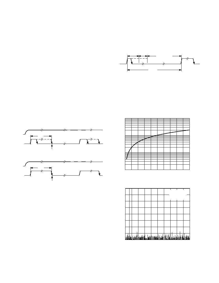
Figure 11 shows the Power vs. Throughput rate for automatic
full power-down.
THROUGHPUT – kSPS
100
10
0.1
0
500
50
100
150
200
250
300
350
400
450
1
POWER
–
mW
Figure 11. Power vs. Throughput
FREQUENCY – Hz
0
–40
–80
0
500
50
dB
100
150
200
250
300
350
400
450
–10
–20
–60
–70
–30
–50
2048 POINT FFT
SAMPLING
1MSPS
FIN = 30kHz
Figure 12. AD7827 SNR
相关PDF资料 |
PDF描述 |
|---|---|
| V300C15M150BG3 | CONVERTER MOD DC/DC 15V 150W |
| AD7572AJRZ10-REEL | IC ADC 12BIT HS LC2MOS 24SOIC |
| V300C15M150BG2 | CONVERTER MOD DC/DC 15V 150W |
| VE-244-MX-F3 | CONVERTER MOD DC/DC 48V 75W |
| SY10EP16VZG TR | IC RCVR HS DIFF 3.3/5V 8SOIC |
相关代理商/技术参数 |
参数描述 |
|---|---|
| AD7828 | 制造商:AD 制造商全称:Analog Devices 功能描述:LC2MOS High Speed 4- & 8-Channel 8-Bit ADCs |
| AD7828BCHIPS | 制造商:未知厂家 制造商全称:未知厂家 功能描述:Single-Ended Data Acquisition System |
| AD7828BQ | 功能描述:IC ADC 8BIT 8CH HS 28-CDIP RoHS:否 类别:集成电路 (IC) >> 数据采集 - 模数转换器 系列:- 标准包装:1 系列:- 位数:14 采样率(每秒):83k 数据接口:串行,并联 转换器数目:1 功率耗散(最大):95mW 电压电源:双 ± 工作温度:0°C ~ 70°C 安装类型:通孔 封装/外壳:28-DIP(0.600",15.24mm) 供应商设备封装:28-PDIP 包装:管件 输入数目和类型:1 个单端,双极 |
| AD7828BR | 功能描述:IC ADC 8BIT 8CH HS 28-SOIC RoHS:否 类别:集成电路 (IC) >> 数据采集 - 模数转换器 系列:- 标准包装:1,000 系列:- 位数:12 采样率(每秒):300k 数据接口:并联 转换器数目:1 功率耗散(最大):75mW 电压电源:单电源 工作温度:0°C ~ 70°C 安装类型:表面贴装 封装/外壳:24-SOIC(0.295",7.50mm 宽) 供应商设备封装:24-SOIC 包装:带卷 (TR) 输入数目和类型:1 个单端,单极;1 个单端,双极 |
| AD7828BR-REEL | 制造商:Analog Devices 功能描述:ADC Single Semiflash 50ksps 8-bit Parallel 28-Pin SOIC W T/R 制造商:Analog Devices 功能描述:CONVERTER I.C. - Tape and Reel |
发布紧急采购,3分钟左右您将得到回复。