参数资料
| 型号: | AD7878KPZ |
| 厂商: | Analog Devices Inc |
| 文件页数: | 16/16页 |
| 文件大小: | 0K |
| 描述: | IC ADC 12BIT W/DSP INT 28-PLCC |
| 产品变化通告: | Product Discontinuance 27/Oct/2011 |
| 标准包装: | 1 |
| 位数: | 12 |
| 采样率(每秒): | 100k |
| 数据接口: | DSP |
| 转换器数目: | 1 |
| 功率耗散(最大): | 95.5mW |
| 电压电源: | 模拟和数字,双 ± |
| 工作温度: | 0°C ~ 70°C |
| 安装类型: | 表面贴装 |
| 封装/外壳: | 28-LCC(J 形引线) |
| 供应商设备封装: | 28-PLCC(11.51x11.51) |
| 包装: | 管件 |
| 输入数目和类型: | 1 个单端,双极 |
AD7878
–9–
REV. A
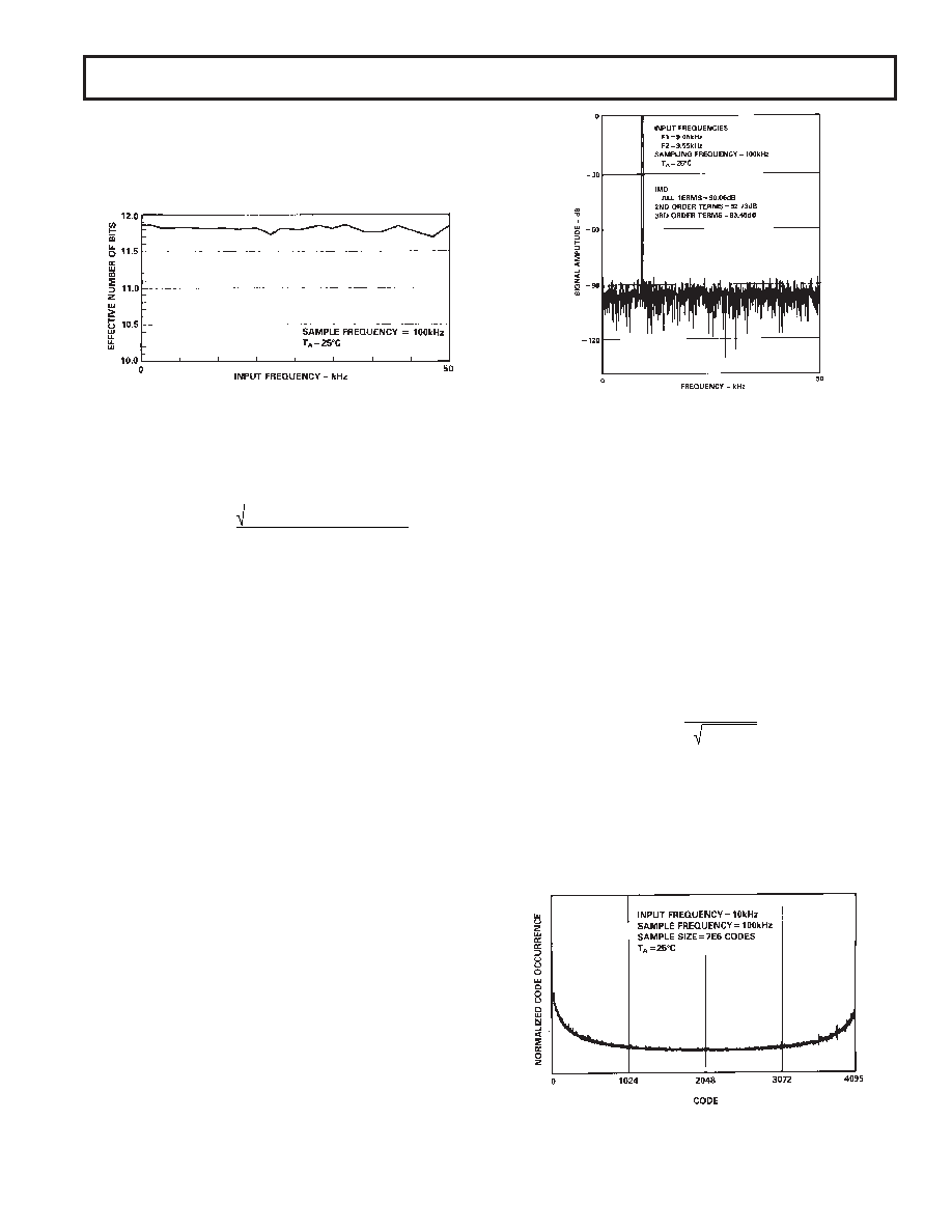
Figure 11 shows a typical plot of effective number of bits versus
frequency for an AD7878KN with a sampling frequency of
100 kHz. The effective number of bits typically falls between
11.7 and 11.85 corresponding to SNR figures of 72.2 and
73.1 dB.
Figure 11. Effective Number of Bits vs. Frequency
Harmonic Distortion
Harmonic Distortion is the ratio of the rms sum of harmonics to
the fundamental. For the AD7878, Total Harmonic Distortion
(THD) is defined as:
THD
= 20 log
(V
2
+V
3
2 +V
4
2 +V
5
2 +V
6
2 )
V1
where V1 is the rms amplitude of the fundamental and V2, V3,
V4, V5 and V6 are the rms amplitudes of the second to the sixth
harmonic. The THD is also derived from the FFT plot of the
ADC output spectrum.
Intermodulation Distortion
With inputs consisting of sine waves at two frequencies, fa and
fb, any active device with nonlinearities will create distortion
products at sum and difference frequencies of mfa + nfb where
m, n = 0, 1, 2, 3 . . . . , etc. Intermodulation terms are those for
which neither m nor n is equal to zero. For example, the second
order terms include (fa + fb) and (fa – fb) while the third order
terms include (2fa + fb), (2fa – fb), (fa + 2fb) and (fa – 2fb).
Using the CCIF standard, where two input frequencies near the
top end of the input bandwidth are used, the second and third
order terms are of different significance. The second order terms
are usually distanced in frequency from the original sine waves,
while the third order terms are usually at a frequency close to the
input frequencies. As a result, the second and third order terms
are specified separately. The calculation of the intermodulation
distortion is as per the THD specification where it is the ratio of
the rms sum of the individual distortion products to the rms am-
plitude of the fundamental expressed in dBs.
Intermodulation distortion is calculated using an FFT algorithm
but, in this case, the input consists of two equal amplitude, low
distortion sine waves. Figure 12 shows a typical IMD plot for
the AD7878.
Peak Harmonic or Spurious Noise
Peak harmonic or spurious noise is defined as the ratio of the
rms value of the next largest component in the ADC output
spectrum (up to FS/2 and excluding dc) to the rms value of the
fundamental. Normally, the value of this specification will be
determined by the largest harmonic in the spectrum, but for
parts where the harmonics are buried in the noise floor the
largest peak will be a noise peak.
Figure 12. AD7878 IMD Plot
Histogram Plot
When a sine wave of a specified frequency is applied to the VIN
input of the AD7878 and several million samples are taken, it is
possible to plot a histogram showing the frequency of occur-
rence of each of the 4096 ADC codes. If a particular step is
wider than the ideal 1 LSB width, then the code associated with
that step will accumulate more counts than for the code for an
ideal step. Likewise, a step narrower than ideal will have fewer
counts. Missing codes are easily seen in the histogram plot because
a missing code means zero counts for a particular code. Large
spikes in the plot indicate large differential nonlinearity.
Figure 13 shows a histogram plot for the AD7878KN with a
sampling frequency of 100 kHz and an input frequency of
25 kHz. For a sine-wave input, a perfect ADC would produce a
cusp probability density function described by the equation:
p (V )
=
1
π ( A2 –V 2 )
where A is the peak amplitude of the sine wave and p (V) is the
probability of occurrence at a voltage V. The histogram plot of
Figure 13 corresponds very well with this cusp shape. The ab-
sence of large spikes in this plot indicates small dynamic differ-
ential nonlinearity (the largest spike in the plot represents less
than 1/4 LSB of DNL error). The AD7878 has no missing
codes under these conditions since no code records zero counts.
Figure 13. AD7878 Histogram Plot
相关PDF资料 |
PDF描述 |
|---|---|
| AD7880CR | IC ADC 12BIT MONO LP 24-SOIC |
| AD7884BQ | IC ADC 16BIT SAMPLING HS 40-CDIP |
| AD7886JD | IC ADC 12BIT SAMPLING HS 28-CDIP |
| AD7887ARZ-REEL | IC ADC 12BIT 2CHAN SRL 8SOIC |
| AD7888ARZ-REEL | IC ADC 12BIT 8CH SRL 16-SOIC |
相关代理商/技术参数 |
参数描述 |
|---|---|
| AD7878KPZ-REEL | 功能描述:IC ADC 12BIT W/DSP 28PLCC RoHS:是 类别:集成电路 (IC) >> 数据采集 - 模数转换器 系列:- 标准包装:1 系列:- 位数:14 采样率(每秒):83k 数据接口:串行,并联 转换器数目:1 功率耗散(最大):95mW 电压电源:双 ± 工作温度:0°C ~ 70°C 安装类型:通孔 封装/外壳:28-DIP(0.600",15.24mm) 供应商设备封装:28-PDIP 包装:管件 输入数目和类型:1 个单端,双极 |
| AD7878LN | 功能描述:IC ADC 12BIT W/DSP INT 28-DIP RoHS:否 类别:集成电路 (IC) >> 数据采集 - 模数转换器 系列:- 标准包装:1 系列:- 位数:14 采样率(每秒):83k 数据接口:串行,并联 转换器数目:1 功率耗散(最大):95mW 电压电源:双 ± 工作温度:0°C ~ 70°C 安装类型:通孔 封装/外壳:28-DIP(0.600",15.24mm) 供应商设备封装:28-PDIP 包装:管件 输入数目和类型:1 个单端,双极 |
| AD7878LP | 制造商:Analog Devices 功能描述:ADC Single SAR 100ksps 12-bit Parallel 28-Pin PLCC 制造商:Rochester Electronics LLC 功能描述:12-BIT ADC IC - Bulk |
| AD7878LPZ | 功能描述:IC ADC 12BIT W/DSP INT 28-PLCC RoHS:是 类别:集成电路 (IC) >> 数据采集 - 模数转换器 系列:- 产品培训模块:Lead (SnPb) Finish for COTS Obsolescence Mitigation Program 标准包装:250 系列:- 位数:12 采样率(每秒):1.8M 数据接口:并联 转换器数目:1 功率耗散(最大):1.82W 电压电源:模拟和数字 工作温度:-40°C ~ 85°C 安装类型:表面贴装 封装/外壳:48-LQFP 供应商设备封装:48-LQFP(7x7) 包装:管件 输入数目和类型:2 个单端,单极 |
| AD7878LPZ-REEL | 功能描述:IC ADC 12BIT W/DSP 28PLCC RoHS:是 类别:集成电路 (IC) >> 数据采集 - 模数转换器 系列:- 标准包装:1 系列:- 位数:14 采样率(每秒):83k 数据接口:串行,并联 转换器数目:1 功率耗散(最大):95mW 电压电源:双 ± 工作温度:0°C ~ 70°C 安装类型:通孔 封装/外壳:28-DIP(0.600",15.24mm) 供应商设备封装:28-PDIP 包装:管件 输入数目和类型:1 个单端,双极 |
发布紧急采购,3分钟左右您将得到回复。