参数资料
| 型号: | AD828ARZ-REEL |
| 厂商: | Analog Devices Inc |
| 文件页数: | 4/12页 |
| 文件大小: | 0K |
| 描述: | IC VIDEO OPAMP DUAL LP 8-SOIC |
| 标准包装: | 2,500 |
| 应用: | 电压反馈 |
| 电路数: | 2 |
| -3db带宽: | 130MHz |
| 转换速率: | 450 V/µs |
| 电流 - 电源: | 14mA |
| 电流 - 输出 / 通道: | 50mA |
| 电压 - 电源,单路/双路(±): | 5 V ~ 36 V,±2.5 V ~ 18 V |
| 安装类型: | 表面贴装 |
| 封装/外壳: | 8-SOIC(0.154",3.90mm 宽) |
| 供应商设备封装: | 8-SOIC |
| 包装: | 带卷 (TR) |
C00879–0–6/02(C)
PRINTED
IN
U.S.A.
–12–
AD828
REV. C
Revision History
Location
Page
6/02–Data Sheet changed from REV. B to REV. C.
Renumbered Figures and TPCs . . . . . . . . . . . . . . . . . . . . . . . . . . . . . . . . . . . . . . . . . . . . . . . . . . . . . . . . . . . . . . . . . . . . . . . . .Global
Changes to Figure 10 . . . . . . . . . . . . . . . . . . . . . . . . . . . . . . . . . . . . . . . . . . . . . . . . . . . . . . . . . . . . . . . . . . . . . . . . . . . . . . . . . . . . 12
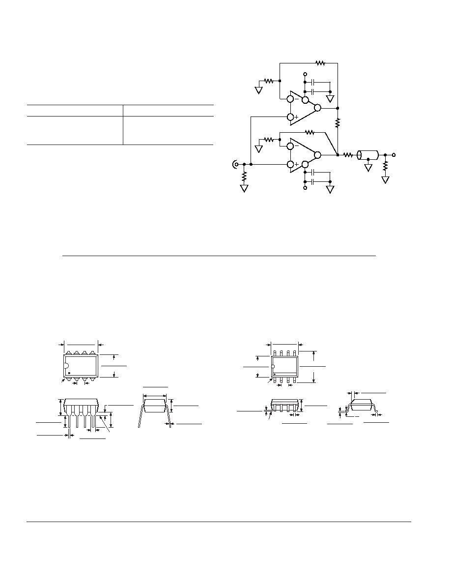
LOW DISTORTION LINE DRIVER
The AD828 can quickly be turned into a powerful, low distor-
tion line driver (see Figure 10). In this arrangement, the AD828
can comfortably drive a 75
back-terminated cable with a
5 MHz, 2 V p-p input, while achieving the harmonic distortion
performance outlined in the following table.
Configuration
2nd Harmonic
1. No Load
–78.5 dBm
2. 150
R
L Only
–63.8 dBm
3. 150
R
L 7.5
R
C
–70.4 dBm
In this application, one half of the AD828 operates at a gain of +2.1
and supplies the current to the load, while the other provides the
overall system gain of +2. This is important for two reasons: the
first is to keep the bandwidth of both amplifiers the same, and
the second is to preserve the AD828’s ability to operate from low
supply voltage. RC varies with the load and must be chosen to
satisfy the following equation:
RC = MRL
where M is defined by [(M + 1) GS = GD] and GD = Driver’s
Gain, GS = System Gain.
+VS
1.1k
RL
RC
7.5
75
0.1 F
1/2
AD828
1
8
1 F
1k
–VS
1k
VIN
1/2
AD828
6
5
7
1k
0.1 F
1 F
4
3
2
Figure 10. Low Distortion Amplifier
OUTLINE DIMENSIONS
8-Lead Plastic Dual-in-Line Package [PDIP]
(N-8)
Dimensions shown in inches and (millimeters)
SEATING
PLANE
0.0598 (1.52)
0.0150 (0.38)
0.2098
(5.33)
MAX
0.0220 (0.56)
0.0142 (0.36)
0.1598 (4.06)
0.1154 (2.93)
0.0697 (1.77)
0.0453 (1.15)
0.1299
(3.30)
MIN
8
1
4
5
PIN 1
0.2799 (7.11)
0.2402 (6.10)
0.1000 (2.54)
BSC
0.4299 (10.92)
0.3480 (8.84)
0.1949 (4.95)
0.1154 (2.93)
0.0150 (0.38)
0.0079 (0.20)
0.3248 (8.25)
0.3000 (7.62)
8-Lead Standard Small Outline Package [SOIC]
(R-8)
Dimensions shown in millimeters and (inches)
0.25 (0.0098)
0.19 (0.0075)
1.27 (0.0500)
0.41 (0.0160)
0.50 (0.0196)
0.25 (0.0099)
45
8
0
1.75 (0.0688)
1.35 (0.0532)
SEATING
PLANE
0.25 (0.0098)
0.10 (0.0040)
85
4
1
5.00 (0.1968)
4.80 (0.1890)
PIN 1
0.1574 (4.00)
0.1497 (3.80)
1.27 (0.0500)
BSC
6.20 (0.2440)
5.80 (0.2284)
0.51 (0.0201)
0.33 (0.0130)
COPLANARITY
CONTROLLING DIMENSIONS ARE IN MILLIMETERS; INCH DIMENSIONS
(IN PARENTHESES) ARE ROUNDED-OFF MILLIMETER EQUIVALENTS FOR
REFERENCE ONLY AND ARE NOT APPROPRIATE FOR USE IN DESIGN
COMPLIANT TO JEDEC STANDARDS MS-012 AA
相关PDF资料 |
PDF描述 |
|---|---|
| VE-J5P-MZ-B1 | CONVERTER MOD DC/DC 13.8V 25W |
| VE-B3P-MU-F1 | CONVERTER MOD DC/DC 13.8V 200W |
| VE-J51-MZ-B1 | CONVERTER MOD DC/DC 12V 25W |
| VE-J4D-MZ-B1 | CONVERTER MOD DC/DC 85V 25W |
| VE-J44-MZ-B1 | CONVERTER MOD DC/DC 48V 25W |
相关代理商/技术参数 |
参数描述 |
|---|---|
| AD828ARZ-REEL7 | 功能描述:IC VIDEO OPAMP DUAL LP 8-SOIC RoHS:是 类别:集成电路 (IC) >> 线性 - 放大器 - 视频放大器和频缓冲器 系列:- 标准包装:1,000 系列:- 应用:驱动器 输出类型:差分 电路数:3 -3db带宽:350MHz 转换速率:1000 V/µs 电流 - 电源:14.5mA 电流 - 输出 / 通道:60mA 电压 - 电源,单路/双路(±):5 V ~ 12 V,±2.5 V ~ 6 V 安装类型:表面贴装 封装/外壳:20-VFQFN 裸露焊盘 供应商设备封装:20-QFN 裸露焊盘(4x4) 包装:带卷 (TR) |
| AD829 | 制造商:AD 制造商全称:Analog Devices 功能描述:High Speed, Low Noise Video Op Amp |
| AD829_04 | 制造商:AD 制造商全称:Analog Devices 功能描述:High Speed, Low Noise Video Op Amp |
| AD829_11 | 制造商:AD 制造商全称:Analog Devices 功能描述:High Speed, Low Noise Video Op Amp |
| AD8290 | 制造商:AD 制造商全称:Analog Devices 功能描述:Low Noise, Low Gain Drift, G = 2000 Instrumentation Amplifier |
发布紧急采购,3分钟左右您将得到回复。