- 您现在的位置:买卖IC网 > PDF目录373943 > AD8323 (Analog Devices, Inc.) 5 V CATV Line Driver Fine Step Output Power Control PDF资料下载
参数资料
| 型号: | AD8323 |
| 厂商: | Analog Devices, Inc. |
| 英文描述: | 5 V CATV Line Driver Fine Step Output Power Control |
| 中文描述: | 5伏精细有线电视线路驱动器输出功率控制步 |
| 文件页数: | 10/16页 |
| 文件大小: | 277K |
| 代理商: | AD8323 |
REV. 0
AD8323
–10–
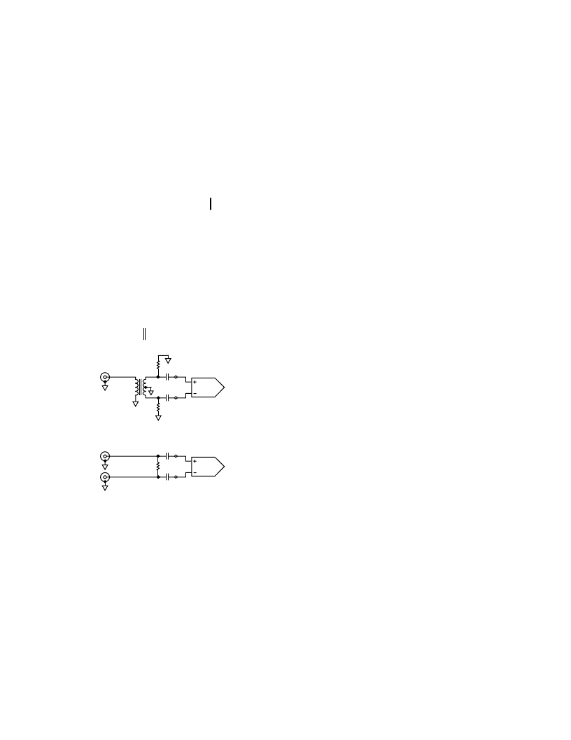
Single-Ended-to-Differential Input (Figure 8, Option 1)
Install the Mini-Circuits T1-6T-KK81 1:1 transformer in the
T1 location of the evaluation board. Place 0
chip resistors at
locations JP1, JP2, and JP3 such that the signal coming in V
IN+
is directed toward the transformer and the differential signal
coming out of the transformer is directed toward TP13 and
TP14. For 75
input impedance, install 39.2
resistors in R5
and R6 located on the back side of the evaluation board. In this
configuration the input signal must be applied to the V
IN+
port
of the evaluation board from a single-ended 75
signal source.
For input impedances other than 75
, the correct value for R5
and R6 can be computed using the following equation:
(
,
Im
R
R
R Desired
pedance
R
5
6
2
800
=
=
=
×
(
)
Differential Input (Figure 8, Option 2)
If a differential signal source is available, it may be applied
directly to both the V
IN+
and V
IN
–
input ports of the evaluation
board. In this case, 0
chip resistors should be placed at loca-
tions R8, JP1, JP2, and JP3 such that the V
IN+
and V
IN
–
signals
are directed toward TP13 and TP14. Referring to Figure 8,
Option 2, a differential input impedance of 150
can be
achieved by using a 165
resistor for R7. For input imped-
ances other than 150
, the correct value for R7 can be computed
using the following equation:
=
(
Desired
pedance
Im
R
)
7 1600
DIFF IN
T1
R5
R6
AD8323
VIN+
AD8323
OPTION 1 DIFFERENTIAL INPUT TERMINATION
OPTION 2 DIFFERENTIAL INPUT TERMINATION
VIN
–
R7
Figure 8. Differential Input Termination Options
Installing the Visual Basic Control Software
To install the
“
CABDRIVE_23
”
evaluation board control soft-
ware, close all Windows applications and then run
“
SETUP.EXE
”
located on Disk 1 of the AD8323 Evaluation Software. Follow
the on-screen instructions and insert Disk 2 when prompted to
do so. Enter the path of the directory into which the software
will be installed and select the button in the upper left corner to
complete the installation.
Running the Software
To invoke the control software, go to START -> PROGRAMS
-> CABDRIVE_23, or select the AD8323.EXE icon from the
directory containing the software.
Controlling the Gain/Attenuation of the AD8323
The slide bar controls the AD8323
’
s gain/attenuation, which is
displayed in dB and in V/V. The gain scales at 0.7526 dB per
LSB with the valid codes being from decimal 0 to 71. The gain
code (i.e., position of the slide bar) is displayed in decimal, binary,
and hexadecimal (see Figure 9).
POWER-UP, POWER-DOWN AND SLEEP
The
“
Power-Up
”
and
“
Power-Down
”
buttons select the mode
of operation of the AD8323 by controlling the logic level on the
asynchronous
PD
pin. The
“
Power-Up
”
button applies a
Logic 1 to the
PD
pin putting the AD8323 in forward transmit
mode. The
“
Power-Down
”
button applies a Logic 0 to the
PD
pin selecting reverse mode, where the forward signal transmission
is disabled while a back termination of 75
is maintained.
Checking the
“
Enable SLEEP Mode
”
box applies a Logic 0 to
the asynchronous
SLEEP
pin, putting the AD8323 into SLEEP
mode.
Memory Section
The
“
MEMORY
”
section of the software provides a convenient
way to alternate between two gain settings. The
“
X->M1
”
but-
ton stores the current value of the gain slide bar into memory
while the
“
RM1
”
button recalls the stored value, returning the
gain slide bar to that level. The
“
X->M2
”
and
“
RM2
”
buttons
work in the same manner.
相关PDF资料 |
PDF描述 |
|---|---|
| AD8323-EVAL | 5 V CATV Line Driver Fine Step Output Power Control |
| AD8325ARU | 5 V CATV Line Driver Fine Step Output Power Control |
| AD8325ARU-REEL | 5 V CATV Line Driver Fine Step Output Power Control |
| AD8325-EVAL | 5 V CATV Line Driver Fine Step Output Power Control |
| AD8325 | Fast Switching Digitally Controlled Variable Gain Amplifier(快速转换数字控制的可变增益放大器) |
相关代理商/技术参数 |
参数描述 |
|---|---|
| AD8323ARU | 制造商:Analog Devices 功能描述:SP Amp Line Driver Amp Single 5.25V 28-Pin TSSOP Tube 制造商:Rochester Electronics LLC 功能描述:TSSOP FINE STEP +5V CATV LINE DRIVER - Bulk |
| AD8323ARU-REEL | 制造商:Analog Devices 功能描述:SP Amp Line Driver Amp Single 5.25V 28-Pin TSSOP T/R 制造商:Rochester Electronics LLC 功能描述:TSSOP FINE STEP +5V CATV LINE DRIVER - Tape and Reel |
| AD8323ARUZ | 制造商:Analog Devices 功能描述:SP Amp Line Driver Amp Single 5.25V 28-Pin TSSOP Tube 制造商:Rochester Electronics LLC 功能描述:TSSOP FINE STEP +5V CATV LINE DRIVER - Bulk |
| AD8323ARUZ-REEL | 制造商:Analog Devices 功能描述:SP Amp Line Driver Amp Single 5.25V 28-Pin TSSOP T/R 制造商:Rochester Electronics LLC 功能描述:TSSOP FINE STEP +5V CATV LINE DRIVER - Tape and Reel |
| AD8323-EVAL | 制造商:AD 制造商全称:Analog Devices 功能描述:5 V CATV Line Driver Fine Step Output Power Control |
发布紧急采购,3分钟左右您将得到回复。