参数资料
| 型号: | AD8531ARTZ-REEL |
| 厂商: | Analog Devices Inc |
| 文件页数: | 7/20页 |
| 文件大小: | 0K |
| 描述: | IC OPAMP GP R-R CMOS SOT23-5 |
| 标准包装: | 10,000 |
| 放大器类型: | 通用 |
| 电路数: | 1 |
| 输出类型: | 满摆幅 |
| 转换速率: | 5 V/µs |
| 增益带宽积: | 3MHz |
| 电流 - 输入偏压: | 5pA |
| 电压 - 输入偏移: | 25000µV |
| 电流 - 电源: | 750µA |
| 电流 - 输出 / 通道: | 250mA |
| 电压 - 电源,单路/双路(±): | 2.7 V ~ 6 V,±1.35 V ~ 3 V |
| 工作温度: | -40°C ~ 85°C |
| 安装类型: | 表面贴装 |
| 封装/外壳: | SC-74A,SOT-753 |
| 供应商设备封装: | SOT-23-5 |
| 包装: | 带卷 (TR) |
AD8531/AD8532/AD8534
Rev. F | Page 15 of 20
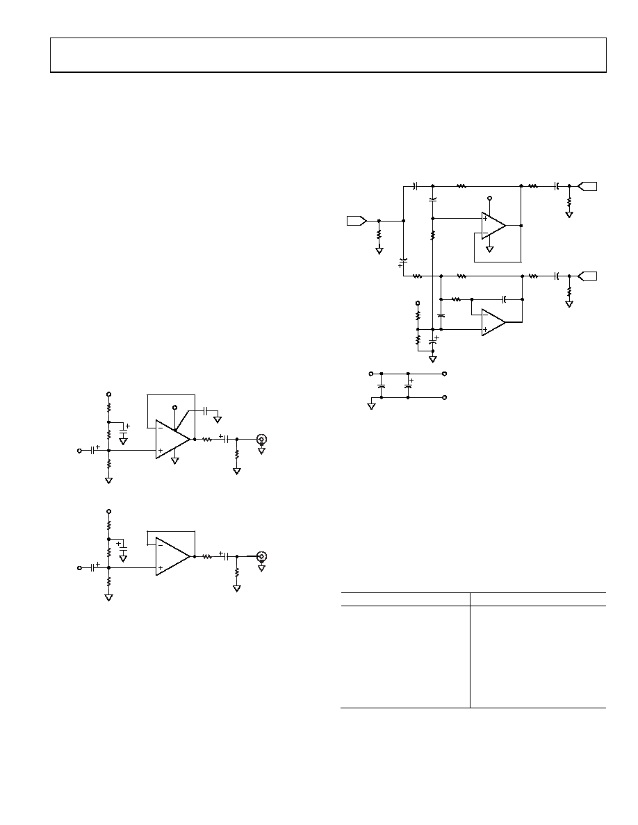
SINGLE-SUPPLY HEADPHONE AMPLIFIER
Because of its speed and large output drive, the AD8531/
AD8532/AD8534 make an excellent headphone driver, as
illustrated in Figure 44. Its low supply operation and rail-to-rail
inputs and outputs give a maximum signal swing on a single
5 V supply. To ensure maximum signal swing available to drive
the headphone, the amplifier inputs are biased to V+/2, which
in this case is 2.5 V. The 100 kΩ resistor to the positive supply
is equally split into two 50 kΩ resistors, with their common
point bypassed by 10 μF to prevent power supply noise from
contaminating the audio signal.
The audio signal is then ac-coupled to each input through a
10 μF capacitor. A large value is needed to ensure that the 20 Hz
audio information is not blocked. If the input already has the
proper dc bias, the ac coupling and biasing resistors are not
required. A 270 μF capacitor is used at the output to couple the
amplifier to the headphone. This value is much larger than that
used for the input because of the low impedance of the head-
phones, which can range from 32 Ω to 600 Ω. An additional 16 Ω
resistor is used in series with the output capacitor to protect the
output stage of the op amp by limiting the capacitor discharge
current. When driving a 48 Ω load, the circuit exhibits less
than 0.3% THD+N at output drive levels of 4 V p-p.
1/2
AD8532
16
50k
270F
LEFT
HEADPHONE
10F
50k
100k
10F
LEFT
INPUT
1/2
AD8532
16
50k
270F
RIGHT
HEADPHONE
10F
50k
100k
10F
RIGHT
INPUT
V
V5V
1F/0.1F
V 5V
010
99-
044
Figure 44. Single-Supply, Stereo Headphone Driver
SINGLE-SUPPLY, 2-WAY LOUDSPEAKER
CROSSOVER NETWORK
Active filters are useful in loudspeaker crossover networks
because of small size, relative freedom from parasitic effects, the
ease of controlling low/high channel drive, and the controlled
driver damping provided by a dedicated amplifier. Both Sallen-
Key (SK) and multiple-feedback (MFB) filter architectures are
useful in implementing active crossover networks. The circuit
shown in Figure 45 is a single-supply, 2-way active crossover
that combines the advantages of both filter topologies.
This active crossover exhibits less than 0.4% THD+N at output
levels of 1.4 V rms using general-purpose, unity-gain HP/LP stages.
In this 2-way example, the LO signal is a dc-to-500 Hz LP woofer
output, and the HI signal is the HP (>500 Hz) tweeter output.
U1B forms an LP section at 500 Hz, while U1A provides an HP
section, covering frequencies ≥500 Hz.
VIN
3
2
1
U1A
AD8532
VS
4
R1
31.6k
C1
0.01F
C2
0.01F
R2
31.6k
R5
31.6k
R6
31.6k
R4
49.9
HI
LO
500Hz
AND UP
DC –
500Hz
6
5
7
C3
0.01F
U1B
AD8532
C4
0.02F
R7
15.8k
R3
49.9 270F
270F
100k
VS
10F
100k
CIN
10F
RIN
100k
0.1F
100F/25V
VS
TO U1
5V
COM
+
100k
+
01099-
0
45
Figure 45. A Single-Supply, 2-Way Active Crossover
The crossover example frequency of 500 Hz can be shifted
lower or higher by frequency scaling of either resistors or
capacitors. In configuring the circuit for other frequencies,
complementary LP/HP action must be maintained between
sections, and component values within the sections must be in
the same ratio. Table 6 provides a design aid to adaptation, with
suggested standard component values for other frequencies.
For additional information on the active filters and active crossover
networks, refer to the data sheet for the OP279, a dual rail-to-
rail, high output current, operational amplifier.
Table 6. RC Component Selection for Various Crossover
Frequencies1
Crossover Frequency (Hz)
100
160 kΩ/0.01 μF
200
80.6 kΩ/0.01 μF
319
49.9 kΩ/0.01 μF
500
31.6 kΩ/0.01 μF
1 k
16 kΩ/0.01 μF
2 k
8.06 kΩ/0.01 μF
5 k
3.16 kΩ/0.01 μF
10 k
1.6 kΩ/0.01 μF
1 Applicable for Filter A = 2.
2 For Sallen-Key stage U1A: R1 = R2, and C1 = C2, and so on.
3 For multiple feedback stage U1B: R6 = R5, R7 = R5/2, and C4 = 2C3.
相关PDF资料 |
PDF描述 |
|---|---|
| 51760-10402002AA | R/A SOLDER REC.PWRBLADE |
| GTC35SGSN-M89 | CONN HEADER 35POS .100 R/A SMD |
| GTC34SGSN-M89 | CONN HEADER 34POS .100 R/A SMD |
| AD8541ARTZ-REEL | IC OPAMP GP R-R CMOS SOT23-5 |
| SMAJ110A-13 | TVS UNI-DIR 110V 400W SMA |
相关代理商/技术参数 |
参数描述 |
|---|---|
| AD8531ARTZ-REEL7 | 功能描述:IC OPAMP GP R-R CMOS SOT23-5 RoHS:是 类别:集成电路 (IC) >> Linear - Amplifiers - Instrumentation 系列:- 特色产品:CMOS Operational Amplifier 标准包装:2,500 系列:- 放大器类型:通用 电路数:2 输出类型:满摆幅 转换速率:1 V/µs 增益带宽积:1MHz -3db带宽:- 电流 - 输入偏压:1pA 电压 - 输入偏移:1000µV 电流 - 电源:900µA 电流 - 输出 / 通道:1mA 电压 - 电源,单路/双路(±):5 V ~ 14.5 V,±2.5 V ~ 7.25 V 工作温度:-40°C ~ 105°C 安装类型:表面贴装 封装/外壳:8-SOIC(0.173",4.40mm 宽) 供应商设备封装:8-SOP 包装:带卷 (TR) 产品目录页面:1372 (CN2011-ZH PDF) 其它名称:BD7562SF-E2TR |
| AD8531ARTZ-REEL7 | 制造商:Analog Devices 功能描述:IC OP-AMP 3MHZ 5V/S SOT-23-5 |
| AD8531ARZ | 功能描述:IC OPAMP GP R-R CMOS 3MHZ 8SOIC RoHS:是 类别:集成电路 (IC) >> Linear - Amplifiers - Instrumentation 系列:- 产品培训模块:Differential Circuit Design Techniques for Communication Applications 标准包装:1 系列:- 放大器类型:RF/IF 差分 电路数:1 输出类型:差分 转换速率:9800 V/µs 增益带宽积:- -3db带宽:2.9GHz 电流 - 输入偏压:3µA 电压 - 输入偏移:- 电流 - 电源:40mA 电流 - 输出 / 通道:- 电压 - 电源,单路/双路(±):3 V ~ 3.6 V 工作温度:-40°C ~ 85°C 安装类型:表面贴装 封装/外壳:16-VQFN 裸露焊盘,CSP 供应商设备封装:16-LFCSP-VQ 包装:剪切带 (CT) 产品目录页面:551 (CN2011-ZH PDF) 其它名称:ADL5561ACPZ-R7CT |
| AD8531ARZ-REEL | 功能描述:IC OPAMP GP R-R CMOS 3MHZ 8SOIC RoHS:是 类别:集成电路 (IC) >> Linear - Amplifiers - Instrumentation 系列:- 特色产品:CMOS Operational Amplifier 标准包装:2,500 系列:- 放大器类型:通用 电路数:2 输出类型:满摆幅 转换速率:1 V/µs 增益带宽积:1MHz -3db带宽:- 电流 - 输入偏压:1pA 电压 - 输入偏移:1000µV 电流 - 电源:900µA 电流 - 输出 / 通道:1mA 电压 - 电源,单路/双路(±):5 V ~ 14.5 V,±2.5 V ~ 7.25 V 工作温度:-40°C ~ 105°C 安装类型:表面贴装 封装/外壳:8-SOIC(0.173",4.40mm 宽) 供应商设备封装:8-SOP 包装:带卷 (TR) 产品目录页面:1372 (CN2011-ZH PDF) 其它名称:BD7562SF-E2TR |
| AD8532 | 制造商:AD 制造商全称:Analog Devices 功能描述:Low Cost, 250 mA Output Single-Supply Amplifiers |
发布紧急采购,3分钟左右您将得到回复。