- 您现在的位置:买卖IC网 > PDF目录17025 > AD9204-65EBZ (Analog Devices Inc)BOARD EVALUATION 65MSPS AD9204 PDF资料下载
参数资料
| 型号: | AD9204-65EBZ |
| 厂商: | Analog Devices Inc |
| 文件页数: | 13/36页 |
| 文件大小: | 0K |
| 描述: | BOARD EVALUATION 65MSPS AD9204 |
| 设计资源: | AD9650,92xx Schematic AD92xx/AD9650 Gerber Files |
| 标准包装: | 1 |
| ADC 的数量: | 2 |
| 位数: | 10 |
| 采样率(每秒): | 65M |
| 数据接口: | 串行,SPI? |
| 输入范围: | 1 ~ 2 Vpp |
| 在以下条件下的电源(标准): | 150.8mW @ 65MSPS |
| 工作温度: | -40°C ~ 85°C |
| 已用 IC / 零件: | AD9204 |
| 已供物品: | 板 |
第1页第2页第3页第4页第5页第6页第7页第8页第9页第10页第11页第12页当前第13页第14页第15页第16页第17页第18页第19页第20页第21页第22页第23页第24页第25页第26页第27页第28页第29页第30页第31页第32页第33页第34页第35页第36页
AD9204
Rev. 0 | Page 20 of 36
Input Common Mode
The analog inputs of the AD9204 are not internally dc-biased.
Therefore, in ac-coupled applications, the user must provide a
dc bias externally. Setting the device so that VCM = AVDD/2 is
recommended for optimum performance, but the device can
function over a wider range with reasonable performance, as
An on-board, common-mode voltage reference is included in
the design and is available from the VCM pin. The VCM pin
must be decoupled to ground by a 0.1 μF capacitor, as described
in the Applications Information section.
50
60
70
80
90
100
0.5
0.6
0.7
0.8
0.9
1.0
1.1
1.2
1.3
S
NR/
S
F
DR
(
d
B
F
S
/d
B
c)
INPUT COMMON-MODE VOLTAGE (V)
SFDR (dBc)
SNR (dBFS)
08
12
2-
1
39
Figure 39. SNR/SFDR vs. Input Common-Mode Voltage,
fIN = 32.1 MHz, fS = 80 MSPS
50
60
70
80
90
100
0.5
0.6
0.7
0.8
0.9
1.0
1.1
1.2
1.3
S
NR/
S
F
DR
(
d
B
F
S
/d
B
c)
INPUT COMMON-MODE VOLTAGE (V)
SFDR (dBc)
SNR (dBFS)
08
12
2-
1
40
Figure 40. SNR/SFDR vs. Input Common-Mode Voltage,
fIN = 10.3 MHz, fS = 20 MSPS
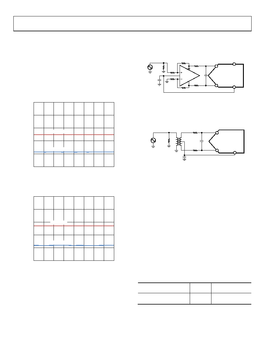
Differential Input Configurations
Optimum performance is achieved while driving the AD9204 in a
differential input configuration. For baseband applications, the
excellent performance and a flexible interface to the ADC.
The output common-mode voltage of the ADA4938-2 is easily
set with the VCM pin of the AD9204 (see Figure 41), and the
driver can be configured in a Sallen-Key filter topology to
provide band limiting of the input signal.
AVDD
VIN
76.8
120
0.1F
33
10pF
200
90
ADA4938-2
ADC
VIN–x
VIN+x
VCM
08
12
2-
00
7
Figure 41. Differential Input Configuration Using the ADA4938-2
For baseband applications below ~10 MHz where SNR is a key
parameter, differential transformer-coupling is the recommended
input configuration. An example is shown in Figure 42. To bias
the analog input, the VCM voltage can be connected to the
center tap of the secondary winding of the transformer.
2V p-p
49.9
0.1F
R
C
ADC
VCM
08
12
2-
0
08
VIN–x
VIN+x
Figure 42. Differential Transformer-Coupled Configuration
The signal characteristics must be considered when selecting
a transformer. Most RF transformers saturate at frequencies
below a few megahertz (MHz). Excessive signal power can
also cause core saturation, which leads to distortion.
At input frequencies in the second Nyquist zone and above, the
noise performance of most amplifiers is not adequate to achieve
the true SNR performance of the AD9204. For applications above
~10 MHz where SNR is a key parameter, differential double balun
coupling is the recommended input configuration (see Figure 44).
An alternative to using a transformer-coupled input at frequencies
in the second Nyquist zone is to use the AD8352 differential driver.
An example is shown in Figure 45. See the AD8352 data sheet
for more information.
In any configuration, the value of Shunt Capacitor C is dependent
on the input frequency and source impedance and may need to
be reduced or removed. Table 9 displays the suggested values to
set the RC network. However, these values are dependent on
the input signal and should be used only as a starting guide.
Table 9. Example RC Network
Frequency Range (MHz)
R Series
(Ω Each)
C Differential (pF)
0 to 70
33
22
70 to 200
125
Open
相关PDF资料 |
PDF描述 |
|---|---|
| EBM30DRSN | CONN EDGECARD 60POS DIP .156 SLD |
| AD9204-80EBZ | BOARD EVALUATION 80MSPS AD9204 |
| DK-V6-EMBD-G-J-XP1 | DEV KIT EMBEDDED VIRTEX 6 |
| 0982660813 | CBL 13POS 0.5MM JMPR TYPE A 2" |
| 0982660816 | CBL 13POS 0.5MM JMPR TYPE D 4" |
相关代理商/技术参数 |
参数描述 |
|---|---|
| AD9204-80EBZ | 功能描述:BOARD EVALUATION 80MSPS AD9204 RoHS:是 类别:编程器,开发系统 >> 评估板 - 模数转换器 (ADC) 系列:- 产品培训模块:Obsolescence Mitigation Program 标准包装:1 系列:- ADC 的数量:1 位数:12 采样率(每秒):94.4k 数据接口:USB 输入范围:±VREF/2 在以下条件下的电源(标准):- 工作温度:-40°C ~ 85°C 已用 IC / 零件:MAX11645 已供物品:板,软件 |
| AD9204BCPZ-20 | 功能描述:IC ADC 10BIT 20MSPS DL 64LFCSP RoHS:是 类别:集成电路 (IC) >> 数据采集 - 模数转换器 系列:- 标准包装:1,000 系列:- 位数:12 采样率(每秒):300k 数据接口:并联 转换器数目:1 功率耗散(最大):75mW 电压电源:单电源 工作温度:0°C ~ 70°C 安装类型:表面贴装 封装/外壳:24-SOIC(0.295",7.50mm 宽) 供应商设备封装:24-SOIC 包装:带卷 (TR) 输入数目和类型:1 个单端,单极;1 个单端,双极 |
| AD9204BCPZ-40 | 功能描述:IC ADC 10BIT 40MSPS DL 64LFCSP RoHS:是 类别:集成电路 (IC) >> 数据采集 - 模数转换器 系列:- 标准包装:1 系列:microPOWER™ 位数:8 采样率(每秒):1M 数据接口:串行,SPI? 转换器数目:1 功率耗散(最大):- 电压电源:模拟和数字 工作温度:-40°C ~ 125°C 安装类型:表面贴装 封装/外壳:24-VFQFN 裸露焊盘 供应商设备封装:24-VQFN 裸露焊盘(4x4) 包装:Digi-Reel® 输入数目和类型:8 个单端,单极 产品目录页面:892 (CN2011-ZH PDF) 其它名称:296-25851-6 |
| AD9204BCPZ-65 | 功能描述:IC ADC 10BIT 65MSPS DL 64LFCSP RoHS:是 类别:集成电路 (IC) >> 数据采集 - 模数转换器 系列:- 其它有关文件:TSA1204 View All Specifications 标准包装:1 系列:- 位数:12 采样率(每秒):20M 数据接口:并联 转换器数目:2 功率耗散(最大):155mW 电压电源:模拟和数字 工作温度:-40°C ~ 85°C 安装类型:表面贴装 封装/外壳:48-TQFP 供应商设备封装:48-TQFP(7x7) 包装:Digi-Reel® 输入数目和类型:4 个单端,单极;2 个差分,单极 产品目录页面:1156 (CN2011-ZH PDF) 其它名称:497-5435-6 |
| AD9204BCPZ-80 | 功能描述:IC ADC 10BIT 80MSPS DL 64LFCSP RoHS:是 类别:集成电路 (IC) >> 数据采集 - 模数转换器 系列:- 标准包装:1 系列:microPOWER™ 位数:8 采样率(每秒):1M 数据接口:串行,SPI? 转换器数目:1 功率耗散(最大):- 电压电源:模拟和数字 工作温度:-40°C ~ 125°C 安装类型:表面贴装 封装/外壳:24-VFQFN 裸露焊盘 供应商设备封装:24-VQFN 裸露焊盘(4x4) 包装:Digi-Reel® 输入数目和类型:8 个单端,单极 产品目录页面:892 (CN2011-ZH PDF) 其它名称:296-25851-6 |
发布紧急采购,3分钟左右您将得到回复。