- 您现在的位置:买卖IC网 > PDF目录2139 > ADA4927-2YCPZ-R2 (Analog Devices Inc)IC OPAMP CF DIFF DUAL LN 24LFCSP PDF资料下载
参数资料
| 型号: | ADA4927-2YCPZ-R2 |
| 厂商: | Analog Devices Inc |
| 文件页数: | 13/24页 |
| 文件大小: | 0K |
| 描述: | IC OPAMP CF DIFF DUAL LN 24LFCSP |
| 特色产品: | ADA4927: Ultralow Distortion Current Feedback Differential ADC Driver |
| 标准包装: | 1 |
| 放大器类型: | 电流反馈 |
| 电路数: | 2 |
| 输出类型: | 差分 |
| 转换速率: | 5000 V/µs |
| -3db带宽: | 2.3GHz |
| 电流 - 输入偏压: | 500nA |
| 电压 - 输入偏移: | 300µV |
| 电流 - 电源: | 20mA |
| 电流 - 输出 / 通道: | 65mA |
| 电压 - 电源,单路/双路(±): | 4.5 V ~ 11 V,±2.25 V ~ 5.5 V |
| 工作温度: | -40°C ~ 105°C |
| 安装类型: | 表面贴装 |
| 封装/外壳: | 24-VFQFN 裸露焊盘,CSP |
| 供应商设备封装: | 24-LFCSP-VQ(4x4) |
| 包装: | 标准包装 |
| 产品目录页面: | 765 (CN2011-ZH PDF) |
| 其它名称: | ADA4927-2YCPZ-R2DKR |
ADA4927-1/ADA4927-2
Rev. A | Page 20 of 24
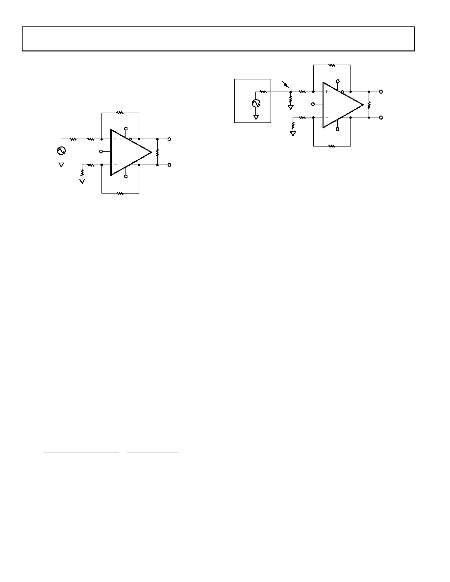
RTS = RTH = RS||RT = 26.5 Ω. Note that VTH is greater than
1 V p-p, which was obtained with RT = 50 Ω. The modified
circuit with the Thevenin equivalent (closest 1% value used for
RTH) of the terminated source and RTS in the lower feedback
loop is shown in Figure 53.
ADA4927
RL VOUT, dm
+VS
–VS
RTH
26.7
RG
348
RG
348
RF
348
RF
348
VOCM
VTH
1.06V p-p
RTS
26.7
07
57
4-
05
3
()()
Figure 53. Thevenin Equivalent and Matched Gain Resistors
Figure 53 presents a tractable circuit with matched
feedback loops that can be easily evaluated.
It is useful to point out two effects that occur with a
terminated input. The first is that the value of RG is increased
in both loops, lowering the overall closed-loop gain. The
second is that VTH is a little larger than 1 V p-p, as it is
when RT = 50 Ω. These two effects have opposite impacts
on the output voltage, and for large resistor values in the
feedback loops (~1 kΩ), the effects essentially cancel each
other out. For small RF and RG, or high gains, however, the
diminished closed-loop gain is not canceled completely by the
The desired differential output in this example is 1 V p-p
because the terminated input signal is 1 V p-p and the
closed-loop gain = 1. The actual differential output voltage,
however, is equal to (1.06 V p-p)(348/374.7) = 0.984 V p-p.
To obtain the desired output voltage of 1 V p-p, a final gain
adjustment can be made by increasing RF without modifying
any of the input circuitry. This is discussed in Step 4.
4.
The feedback resistor value is modified as a final gain
adjustment to obtain the desired output voltage.
To make the output voltage VOUT = 1 V p-p, RF must be
calculated using the following formula:
()(
)
35
06
.
1
Ω
374.7
1
,
=
=
+
p
V
p
V
R
V
Desired
TH
TS
G
dm
OUT
F =
R
The closest standard 1% values to 353 Ω are 348 Ω and
357 Ω. Choosing 357 Ω for RF gives a differential output
voltage of 1.01 V p-p. The closed-loop bandwidth is
diminished by a factor of approximately 348/357 from
what it would be with RF = 348 Ω due to the inversely
proportional relationship between RF and closed-loop
gain that is characteristic of current feedback amplifiers.
The final circuit is shown in Figure 54.
ADA4927
RL
VOUT, dm
1.01V p-p
+VS
–VS
RS
50
RG
348
RG
348
RF
357
RF
357
VOCM
VS
2V p-p
1V p-p
RT
56.2
RTS
26.7
07
574
-05
4
Figure 54. Terminated Single-Ended-to-Differential System with G = 1
INPUT COMMON-MODE VOLTAGE RANGE
The ADA4927 input common-mode range is centered between the
two supply rails, in contrast to other ADC drivers with level-shifted
input ranges, such as the ADA4937. The centered input common-
mode range is best suited to ac-coupled, differential-to-differential,
and dual supply applications.
For operation with ±5 V supplies, the input common-mode
range at the summing nodes of the amplifier is specified as
3.5 V to +3.5 V and is specified as +1.3 V to +3.7 V with a
single +5 V supply. To avoid nonlinearities, the voltage swing
at the +IN and IN terminals must be confined to these ranges.
INPUT AND OUTPUT CAPACITIVE AC COUPLING
Input ac coupling capacitors can be inserted between the source
and RG. This ac coupling blocks the flow of the dc common-
mode feedback current and causes the ADA4927 dc input
common-mode voltage to equal the dc output common-mode
voltage. These ac coupling capacitors must be placed in both
loops to keep the feedback factors matched.
Output ac coupling capacitors can be placed in series between
each output and its respective load. See Figure 58 for an example
that uses input and output capacitive ac coupling.
SETTING THE OUTPUT COMMON-MODE VOLTAGE
The VOCM pin of the ADA4927 is internally biased with a voltage
divider comprising two 10 kΩ resistors at a voltage approximately
equal to the midsupply point, [(+VS) + (VS)]/2. Because of this
internal divider, the VOCM pin sources and sinks current, depending
on the externally applied voltage and its associated source resistance.
Relying on the internal bias results in an output common-mode
voltage that is within about 100 mV of the expected value.
In cases where accurate control of the output common-mode level
is required, it is recommended that an external source or resistor
divider be used with source resistance less than 100 Ω. The output
common-mode offset listed in the Specifications section presumes
that the VOCM input is driven by a low impedance voltage source.
It is also possible to connect the VOCM input to a common-mode
level (CML) output of an ADC; however, care must be taken to
ensure that the output has sufficient drive capability. The input
impedance of the VOCM pin is approximately 10 kΩ. If multiple
ADA4927 devices share one ADC reference output, a buffer may
be necessary to drive the parallel inputs.
相关PDF资料 |
PDF描述 |
|---|---|
| ADA4930-1YCPZ-R2 | IC DIFF AMP 1.35GHZ 16-LFCSP |
| ADA4932-1YCPZ-RL | IC AMP DIFF LP 80MA 16LFCSP |
| ADA4939-2YCPZ-R7 | IC AMP DIFF DUAL ULDIST 24LFCSP |
| ADA4940-1ARZ-R7 | IC DIFF ADC DVR 18BIT LN 8SOIC |
| ADA4950-1YCPZ-RL | IC AMP DIFF LP 114MA 16LFCSP |
相关代理商/技术参数 |
参数描述 |
|---|---|
| ADA4927-2YCPZ-R7 | 功能描述:IC OPAMP CF DIFF DUAL LN 24LFCSP RoHS:是 类别:集成电路 (IC) >> Linear - Amplifiers - Instrumentation 系列:- 标准包装:2,500 系列:Excalibur™ 放大器类型:J-FET 电路数:1 输出类型:- 转换速率:45 V/µs 增益带宽积:10MHz -3db带宽:- 电流 - 输入偏压:20pA 电压 - 输入偏移:490µV 电流 - 电源:1.7mA 电流 - 输出 / 通道:48mA 电压 - 电源,单路/双路(±):4.5 V ~ 38 V,±2.25 V ~ 19 V 工作温度:-40°C ~ 85°C 安装类型:表面贴装 封装/外壳:8-SOIC(0.154",3.90mm 宽) 供应商设备封装:8-SOIC 包装:带卷 (TR) |
| ADA4927-2YCPZ-RL | 功能描述:IC OPAMP CF DIFF DUAL LN 24LFCSP RoHS:是 类别:集成电路 (IC) >> Linear - Amplifiers - Instrumentation 系列:- 标准包装:2,500 系列:Excalibur™ 放大器类型:J-FET 电路数:1 输出类型:- 转换速率:45 V/µs 增益带宽积:10MHz -3db带宽:- 电流 - 输入偏压:20pA 电压 - 输入偏移:490µV 电流 - 电源:1.7mA 电流 - 输出 / 通道:48mA 电压 - 电源,单路/双路(±):4.5 V ~ 38 V,±2.25 V ~ 19 V 工作温度:-40°C ~ 85°C 安装类型:表面贴装 封装/外壳:8-SOIC(0.154",3.90mm 宽) 供应商设备封装:8-SOIC 包装:带卷 (TR) |
| ADA4930-1 | 制造商:AD 制造商全称:Analog Devices 功能描述:Ultralow Noise Drivers for Low Voltage ADCs |
| ADA4930-1SCPZ-EPR2 | 制造商:Analog Devices 功能描述:ULTRALOW DIST LOW VLTG ADC DRIVER - Tape and Reel 制造商:Analog Devices 功能描述:Differential Amplifiers UltraLow Dist Low Vltg ADC Driver |
| ADA4930-1SCPZ-EPR7 | 制造商:Analog Devices 功能描述:ULTRALOW DIST LOW VLTG ADC DRIVER - Tape and Reel 制造商:Analog Devices 功能描述:IC OPAMP DIFF 1.35GHZ 16LFCSP |
发布紧急采购,3分钟左右您将得到回复。