- 您现在的位置:买卖IC网 > PDF目录10327 > ADAU1513ACPZ-RL (Analog Devices Inc)IC AMP AUDIO PWR 23W 48LFCSP PDF资料下载
参数资料
| 型号: | ADAU1513ACPZ-RL |
| 厂商: | Analog Devices Inc |
| 文件页数: | 1/16页 |
| 文件大小: | 0K |
| 描述: | IC AMP AUDIO PWR 23W 48LFCSP |
| 产品变化通告: | ADAU1513,1590 Discontinuation 09/Apr/2012 |
| 标准包装: | 2,500 |
| 类型: | D 类 |
| 输出类型: | 2 通道(立体声) |
| 在某负载时最大输出功率 x 通道数量: | 23W x 2 @ 4 欧姆 |
| 电源电压: | 9 V ~ 18 V |
| 特点: | 差分输入,PWM,短路和热保护 |
| 安装类型: | 表面贴装 |
| 供应商设备封装: | 48-LFCSP-VQ(7x7) |
| 封装/外壳: | 48-VFQFN 裸露焊盘,CSP |
| 包装: | 带卷 (TR) |
Class-D Audio Power Stage
ADAU1513
Rev. 0
Information furnished by Analog Devices is believed to be accurate and reliable. However, no
responsibilityis assumedbyAnalogDevicesforitsuse,norforanyinfringements of patents or other
rightsofthirdpartiesthatmayresultfromitsuse.Specificationssubjecttochangewithoutnotice.No
license is granted by implication or otherwise under any patent or patent rights of Analog Devices.
Trademarksandregisteredtrademarksarethepropertyoftheirrespectiveowners.
One Technology Way, P.O. Box 9106, Norwood, MA 02062-9106, U.S.A.
Tel: 781.329.4700
www.analog.com
Fax: 781.461.3113
2007 Analog Devices, Inc. All rights reserved.
FEATURES
Integrated stereo power stage
RDS-ON < 0.3 Ω (per transistor)
Efficiency > 90%
Short-circuit protection
Overtemperature protection
APPLICATIONS
Flat panel televisions
PC audio systems
Mini components
GENERAL DESCRIPTION
The ADAU1513 is a 2-channel bridge-tied load (BTL)
Class-D audio power stage. The power stage can drive the
speaker loads of 4 Ω at up to 15 W per channel at high
efficiency. The 4-channel audio system can be formed when
used with an ADAV4201 pulse-width modulator (PWM)
processor using two ADAU1513s. The power stage accepts a
3.3 V logic differential PWM as input from an ADAV4201
processor. The power stage comprises thermal and output
short-circuit protection with logic-level error flag outputs for
interfacing to a system microcontroller along with reset and
mute control of the power stage. The power stage operates from
a range of power supply voltages from 9 V up to 18 V. The low
power digital logic operates from a 3.3 V supply. The power
stage can be used with modulators other than the ADAV4201.
Contact your local sales department for application assistance.
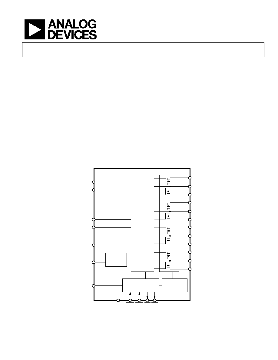
FUNCTIONAL BLOCK DIAGRAM
A1
PVDD
OUTL+
PGND
A2
B1
PVDD
OUTL–
PGND
B2
C1
PVDD
OUTR+
PGND
C2
D1
PVDD
OUTR–
PGND
D2
LEVEL SHIFT
AND DEAD
TIME CONTROL
TEMPERATURE/
OVERCURRENT
PROTECTION
MODE CONTROL
LOGIC
ADAU1513
VOLTAGE
REFERENCE
INL+
INL–
INR+
INR–
AVDD
AGND
DVDD
DGND
OTW
ERR
MUTE
STDN
06
75
0-
0
01
Figure 1.
OBSOLETE
相关PDF资料 |
PDF描述 |
|---|---|
| VE-24H-IU-S | CONVERTER MOD DC/DC 52V 200W |
| ADAU1513ACPZ | IC AMP AUDIO PWR 23W 48LFCSP |
| VE-24F-IU-S | CONVERTER MOD DC/DC 72V 200W |
| VE-24B-IU-S | CONVERTER MOD DC/DC 95V 200W |
| VE-244-IU-S | CONVERTER MOD DC/DC 48V 200W |
相关代理商/技术参数 |
参数描述 |
|---|---|
| ADAU1513ACPZ-RL7 | 功能描述:IC AMP AUDIO PWR 23W 48LFCSP RoHS:是 类别:集成电路 (IC) >> 线性 - 音頻放大器 系列:- 产品培训模块:Lead (SnPb) Finish for COTS Obsolescence Mitigation Program 标准包装:2,500 系列:DirectDrive® 类型:H 类 输出类型:耳机,2-通道(立体声) 在某负载时最大输出功率 x 通道数量:35mW x 2 @ 16 欧姆 电源电压:1.62 V ~ 1.98 V 特点:I²C,麦克风,静音,短路保护,音量控制 安装类型:表面贴装 供应商设备封装:25-WLP(2.09x2.09) 封装/外壳:25-WFBGA,WLCSP 包装:带卷 (TR) |
| ADAU1513ASVZ | 制造商:Analog Devices 功能描述: |
| ADAU1513ASVZ-RL | 制造商:Analog Devices 功能描述: |
| ADAU1513ASVZ-RL7 | 制造商:AD 制造商全称:Analog Devices 功能描述:Class-D Audio Power Stage |
| ADAU1590 | 制造商:AD 制造商全称:Analog Devices 功能描述:Class-D Audio Power Amplifier |
发布紧急采购,3分钟左右您将得到回复。