- 您现在的位置:买卖IC网 > PDF目录10327 > ADAU1513ACPZ-RL (Analog Devices Inc)IC AMP AUDIO PWR 23W 48LFCSP PDF资料下载
参数资料
| 型号: | ADAU1513ACPZ-RL |
| 厂商: | Analog Devices Inc |
| 文件页数: | 5/16页 |
| 文件大小: | 0K |
| 描述: | IC AMP AUDIO PWR 23W 48LFCSP |
| 产品变化通告: | ADAU1513,1590 Discontinuation 09/Apr/2012 |
| 标准包装: | 2,500 |
| 类型: | D 类 |
| 输出类型: | 2 通道(立体声) |
| 在某负载时最大输出功率 x 通道数量: | 23W x 2 @ 4 欧姆 |
| 电源电压: | 9 V ~ 18 V |
| 特点: | 差分输入,PWM,短路和热保护 |
| 安装类型: | 表面贴装 |
| 供应商设备封装: | 48-LFCSP-VQ(7x7) |
| 封装/外壳: | 48-VFQFN 裸露焊盘,CSP |
| 包装: | 带卷 (TR) |
ADAU1513
Rev. 0 | Page 13 of 16
amplifier starts functioning again. This cycle repeats itself
depending on the input signal conditions and the temperature
of the die. This option allows part operation that is safely below
the shutdown temperature of 150°C and allows the amplifier to
recover itself without the need for microcontroller intervention.
Option 2: Using ERR
Option 2 is similar to Option 1 if the ERR pin can be tied to
MUTE instead of OTW. See the circuit in Figure 29.
06
75
0
-02
8
ADAU1513
ERR
TO MUTE
LOGIC INPUT
D1
1N4148
DVDD
R1
100k
MUTE
C1
47F
9
15
Figure 29. Option 2 Schematic for Autorecovery
In this case, the part goes into shutdown mode due to any of the
error-generating events like output overcurrent, overtemperature,
missing PVDD or DVDD, or clock loss. The part recovers itself
based on the same circuit operation in Figure 28.
However, if the part goes into error mode due to overtempera-
ture, then the device would have reached its maximum limit of
150°C (15°C to 20°C higher than Option 1). If it goes into error
mode due to an overcurrent from a short circuit on the speaker
outputs, then the part will keep itself recycling on and off until
the short circuit is removed.
It is possible that, with this operation, the part is subjected to a
much higher temperature and current stress continuously. This,
in turn, reduces the part’s reliability in the long term. Therefore,
using Option 1 for autorecovery from the thermal protection
and using the system microcontroller to indicate to the user of
an error condition is recommended.
MUTE AND STDN
The MUTE and STDN are 3.3 V logic-compatible inputs used
to control the turn-on/turn-off for ADAU1513.
The STDN input is active low when the STDN pin is pulled low
and the device is in its energy-saving mode. The power stage is
in high-Z state. The high logic level input on the STDN pin will
wake up the device. The logic circuits are running internally but
the power stage is still in high-Z state.
When the MUTE pin is pulled high, the power stage is active
and starts responding to PWM inputs. The low level on the
MUTE pin disables the power stage and is recommended to be
used to mute the audio output. See the Power-Up/Power-Down
Sequence section for more details.
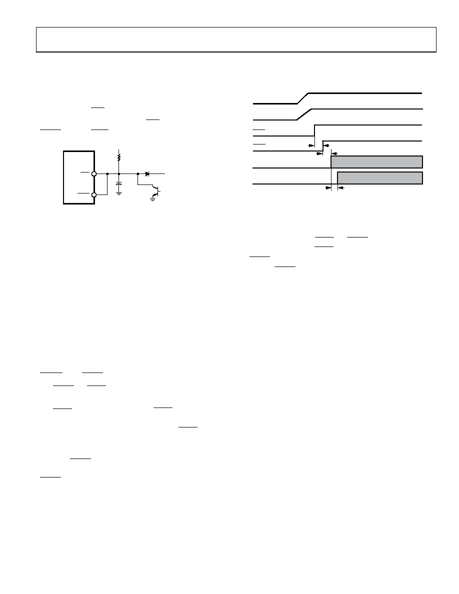
POWER-UP/POWER-DOWN SEQUENCE
Figure 30 shows the recommended power-up sequence for the
ADAU1513.
06
75
0-
02
9
AVDD/DVDD
PVDD
STDN
OUTx+/OUTx–
INx+/INx–
MUTE
tSET
tPDL-H
tWAIT
Figure 30. Recommended Power-Up Sequence
The ADAU1513 does not have any pop-and-click suppression
circuits; therefore, care must be taken during the power-up. The
power stage stays in Hi-Z on power-up. However, it is recom-
mended to ensure that STDN and MUTE are held low during
initial power-up. First, STDN should be pulled high followed by
MUTE to turn on the power stage. The power stage turns on
after the MUTE signal is pulled high and responds to PWM
inputs after a small propagation delay of 200 μs.
The special turn-on sequence may be necessary depending on
the PWM used to prevent the turn-on pop or click. However, if
the ADAV4201 processor is used, the processor has a built-in
special turn-on PWM sequence. The processor sends a unique
PWM input start sequence that ensures soft turn-on.
If another modulator is used, care must be taken to ensure that
the modulator has built-in pop-and-click suppression. Also,
because the power stage does not track the PWM inputs, it is
recommended to use the system microcontroller to ensure that
the modulator is ready to send the PWM sequence before
turning on the power stage.
Similarly, for muting the amplifier, it may be necessary to
supply a special muting PWM sequence for minimum pop and
click. The ADAV4201 processor has a built-in feature that takes
care of this need. If any other modulator is used, care must be
taken during muting of the power stage.
The system microcontroller can be used to handle the
mute/unmute of the power stage as well as a modulator.
The error outputs of the power stage should be connected to
the microcontroller port. This error flag can be used to inform
the modulator that the power stage is shut down and to mute
the PWM inputs. On removal of the error condition, the
microcontroller should initiate an unmute sequence to mini-
mize pop and click while power stage is turning on/turning off.
The ADAU1513 uses three separate supplies: AVDD (3.3 V
analog for internal reference), DVDD (3.3 V digital for control
logic and clock oscillator), and PVDD (9 V to 18 V power stage
and level shifter). Separate pins are provided for the AVDD,
OBSOLETE
相关PDF资料 |
PDF描述 |
|---|---|
| VE-24H-IU-S | CONVERTER MOD DC/DC 52V 200W |
| ADAU1513ACPZ | IC AMP AUDIO PWR 23W 48LFCSP |
| VE-24F-IU-S | CONVERTER MOD DC/DC 72V 200W |
| VE-24B-IU-S | CONVERTER MOD DC/DC 95V 200W |
| VE-244-IU-S | CONVERTER MOD DC/DC 48V 200W |
相关代理商/技术参数 |
参数描述 |
|---|---|
| ADAU1513ACPZ-RL7 | 功能描述:IC AMP AUDIO PWR 23W 48LFCSP RoHS:是 类别:集成电路 (IC) >> 线性 - 音頻放大器 系列:- 产品培训模块:Lead (SnPb) Finish for COTS Obsolescence Mitigation Program 标准包装:2,500 系列:DirectDrive® 类型:H 类 输出类型:耳机,2-通道(立体声) 在某负载时最大输出功率 x 通道数量:35mW x 2 @ 16 欧姆 电源电压:1.62 V ~ 1.98 V 特点:I²C,麦克风,静音,短路保护,音量控制 安装类型:表面贴装 供应商设备封装:25-WLP(2.09x2.09) 封装/外壳:25-WFBGA,WLCSP 包装:带卷 (TR) |
| ADAU1513ASVZ | 制造商:Analog Devices 功能描述: |
| ADAU1513ASVZ-RL | 制造商:Analog Devices 功能描述: |
| ADAU1513ASVZ-RL7 | 制造商:AD 制造商全称:Analog Devices 功能描述:Class-D Audio Power Stage |
| ADAU1590 | 制造商:AD 制造商全称:Analog Devices 功能描述:Class-D Audio Power Amplifier |
发布紧急采购,3分钟左右您将得到回复。