参数资料
| 型号: | ADC0804LCN |
| 厂商: | Intersil |
| 文件页数: | 9/17页 |
| 文件大小: | 0K |
| 描述: | IC ADC 8-BIT 10KSPS 1LSB 20-DIP |
| 标准包装: | 1,080 |
| 位数: | 8 |
| 采样率(每秒): | 10k |
| 数据接口: | 并联 |
| 转换器数目: | 1 |
| 电压电源: | 单电源 |
| 工作温度: | 0°C ~ 70°C |
| 安装类型: | 通孔 |
| 封装/外壳: | 20-DIP(0.300",7.62mm) |
| 供应商设备封装: | 20-PDIP |
| 包装: | 管件 |
| 输入数目和类型: | 1 个差分,单极 |
| 其它名称: | ADC0804LCNIN ADC0804LCNIN-ND |
17
All Intersil products are manufactured, assembled and tested utilizing ISO9000 quality systems.
Intersil Corporation’s quality certifications can be viewed at website www.intersil.com/quality/iso.asp.
Intersil products are sold by description only. Intersil Corporation reserves the right to make changes in circuit design and/or specifications at any time without notice.
Accordingly, the reader is cautioned to verify that data sheets are current before placing orders. Information furnished by Intersil is believed to be accurate and reliable. How-
ever, no responsibility is assumed by Intersil or its subsidiaries for its use; nor for any infringements of patents or other rights of third parties which may result from its use. No
license is granted by implication or otherwise under any patent or patent rights of Intersil or its subsidiaries.
For information regarding Intersil Corporation and its products, see web site www.intersil.com
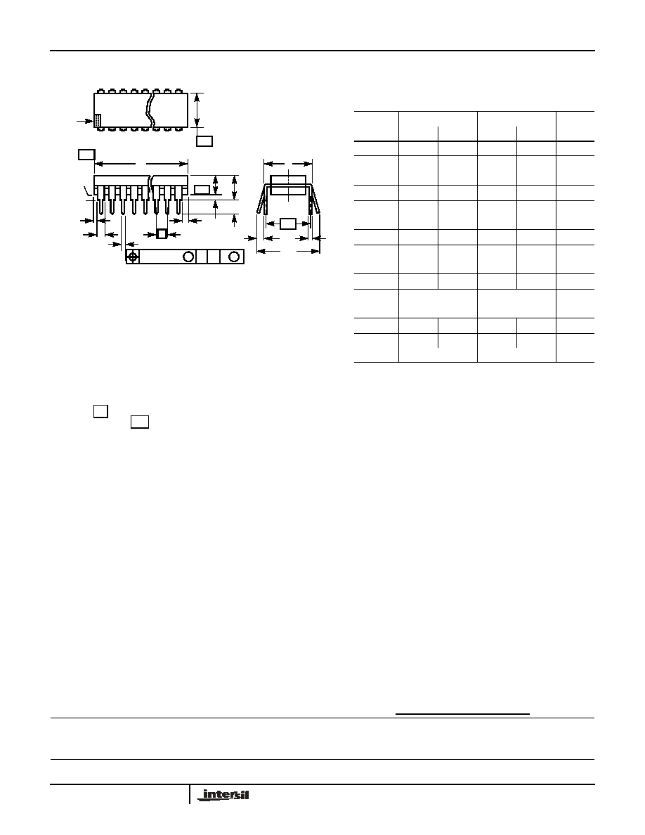
ADC0803, ADC0804
Dual-In-Line Plastic Packages (PDIP)
NOTES:
1. Controlling Dimensions: INCH. In case of conflict between English
and Metric dimensions, the inch dimensions control.
2. Dimensioning and tolerancing per ANSI Y14.5M-1982.
3. Symbols are defined in the “MO Series Symbol List” in Section 2.2
of Publication No. 95.
4. Dimensions A, A1 and L are measured with the package seated in
JEDEC seating plane gauge GS-3.
5. D, D1, and E1 dimensions do not include mold flash or protrusions.
Mold flash or protrusions shall not exceed 0.010 inch (0.25mm).
6. E and
are measured with the leads constrained to be perpen-
dicular to datum
.
7. eB and eC are measured at the lead tips with the leads uncon-
strained. eC must be zero or greater.
8. B1 maximum dimensions do not include dambar protrusions. Dam-
bar protrusions shall not exceed 0.010 inch (0.25mm).
9. N is the maximum number of terminal positions.
10. Corner leads (1, N, N/2 and N/2 + 1) for E8.3, E16.3, E18.3, E28.3,
E42.6 will have a B1 dimension of 0.030 - 0.045 inch (0.76 - 1.14mm).
eA
-C-
CL
E
eA
C
eB
eC
-B-
E1
INDEX
12 3
N/2
N
AREA
SEATING
BASE
PLANE
-C-
D1
B1
B
e
D
D1
A
A2
L
A1
-A-
0.010 (0.25)
C A
M
BS
E20.3 (JEDEC MS-001-AD ISSUE D)
20 LEAD DUAL-IN-LINE PLASTIC PACKAGE
SYMBOL
INCHES
MILLIMETERS
NOTES
MIN
MAX
MIN
MAX
A
-
0.210
-
5.33
4
A1
0.015
-
0.39
-
4
A2
0.115
0.195
2.93
4.95
-
B
0.014
0.022
0.356
0.558
-
B1
0.045
0.070
1.55
1.77
8
C
0.008
0.014
0.204
0.355
-
D
0.980
1.060
24.89
26.9
5
D1
0.005
-
0.13
-
5
E
0.300
0.325
7.62
8.25
6
E1
0.240
0.280
6.10
7.11
5
e
0.100 BSC
2.54 BSC
-
eA
0.300 BSC
7.62 BSC
6
eB
-
0.430
-
10.92
7
L
0.115
0.150
2.93
3.81
4
N20
20
9
Rev. 0 12/93
相关PDF资料 |
PDF描述 |
|---|---|
| ADC0820CCM+ | IC ADC 8-BIT HS 20-SOIC |
| ADF4001BRU | IC CLOCK GEN PLL 16-TSSOP |
| ADF4002BRUZ-RL7 | IC PLL FREQUENCY SYNTH 16-TSSOP |
| ADF4007BCPZ-RL7 | IC DIVIDER/PLL SYNTHESZR 20LFCSP |
| ADF4106BRU | IC PLL FREQ SYNTHESIZER 16-TSSOP |
相关代理商/技术参数 |
参数描述 |
|---|---|
| ADC0804LCN | 制造商:Texas Instruments 功能描述:IC 8BIT ADC DIP20 804 |
| ADC0804LCN/A+ | 制造商:未知厂家 制造商全称:未知厂家 功能描述:Analog-to-Digital Converter, 8-Bit |
| ADC0804LCN/B+ | 制造商:未知厂家 制造商全称:未知厂家 功能描述:Analog-to-Digital Converter, 8-Bit |
| ADC0804LCN/NOPB | 功能描述:模数转换器 - ADC 8B UP COMPATIBLE ADC RoHS:否 制造商:Texas Instruments 通道数量:2 结构:Sigma-Delta 转换速率:125 SPs to 8 KSPs 分辨率:24 bit 输入类型:Differential 信噪比:107 dB 接口类型:SPI 工作电源电压:1.7 V to 3.6 V, 2.7 V to 5.25 V 最大工作温度:+ 85 C 安装风格:SMD/SMT 封装 / 箱体:VQFN-32 |
| ADC0804LCN/NOPB | 制造商:Texas Instruments 功能描述:A/D Converter (A-D) IC |
发布紧急采购,3分钟左右您将得到回复。