- 您现在的位置:买卖IC网 > PDF目录378278 > ADC081S051CISDX (NATIONAL SEMICONDUCTOR CORP) Single Channel, 500 kSPS, 8-Bit A/D Converter PDF资料下载
参数资料
| 型号: | ADC081S051CISDX |
| 厂商: | NATIONAL SEMICONDUCTOR CORP |
| 元件分类: | ADC |
| 英文描述: | Single Channel, 500 kSPS, 8-Bit A/D Converter |
| 中文描述: | 1-CH 8-BIT SUCCESSIVE APPROXIMATION ADC, SERIAL ACCESS, PDSO6 |
| 封装: | LLP-6 |
| 文件页数: | 5/13页 |
| 文件大小: | 621K |
| 代理商: | ADC081S051CISDX |
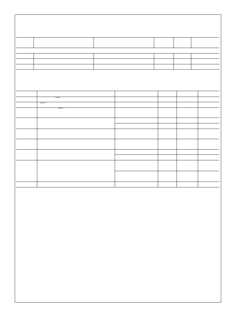
ADC081S051 Converter Electrical Characteristics
(Note 9) (Continued)
The following specifications apply for V
= +2.7V to 5.25V, GND = 0V, f
= 4 MHz to 10 MHz,
f
= 200 kSPS to 500 kSPS, unless otherwise noted.
Boldface limits apply for T
A
= T
MIN
to T
MAX
: all other limits T
A
=
25C.
Symbol
Parameter
Conditions
Typical
Limits
(Note 9)
Units
AC ELECTRICAL CHARACTERISTICS
t
QUIET
(Note 10)
t
AD
Aperture Delay
t
AJ
Aperture Jitter
50
ns (min)
ns
ps
3
30
ADC081S051 Timing Specifications
The following specifications apply for V
= +2.7V to 5.25V, GND = 0V, f
SCLK
= 4 MHz to 10 MHz,
f
SAMPLE
= 200 kSPS to 500 kSPS,
Boldface limits apply for T
A
= T
MIN
MAX
: all other limits T
A
= 25C.
Symbol
Parameter
t
CS
Minimum CS Pulse Width
t
SU
CS to SCLK Setup Time
Delay from CS Until SDATA TRI-STATE
Disabled (Note 11)
Data Access Time after SCLK Falling Edge
(Note 12)
Conditions
Typical
Limits
10
10
Units
ns (min)
ns (min)
t
EN
20
ns (max)
t
ACC
V
A
= +2.7 to +3.6
V
A
= +4.75 to +5.25
40
20
ns (max)
ns (max)
t
CL
SCLK Low Pulse Width
0.4 x
t
SCLK
0.4 x
t
SCLK
7
5
25
6
25
5
ns (min)
t
CH
SCLK High Pulse Width
ns (min)
t
H
SCLK to Data Valid Hold Time
V
A
= +2.7 to +3.6
V
A
= +4.75 to +5.25
ns (min)
ns (min)
ns (max)
ns (min)
ns (max)
ns (min)
μs
t
DIS
SCLK Falling Edge to SDATA High
Impedance (Note 13)
V
A
= +2.7 to +3.6
V
A
= +4.75 to +5.25
t
POWER-UP
Power-Up Time from Full Power-Down
1
Note 1:
Absolute Maximum Ratings indicate limits beyond which damage to the device may occur. Operating Ratings indicate conditions for which the device is
functional, but do not guarantee specific performance limits. For guaranteed specifications and test conditions, see the Electrical Characteristics. The guaranteed
specifications apply only for the test conditions listed. Some performance characteristics may degrade when the device is not operated under the listed test
conditions.
Note 2:
All voltages are measured with respect to GND = 0V, unless otherwise specified.
Note 3:
When the input voltage at any pin exceeds the power supply (that is, V
<
GND or V
>
V
), the current at that pin should be limited to 10 mA. The 20
mA maximum package input current rating limits the number of pins that can safely exceed the power supplies with an input current of 10 mA to two. The Absolute
Maximum Rating specification does not apply to the V
A
pin. The current into the V
A
pin is limited by the Analog Supply Voltage specification.
Note 4:
The absolute maximum junction temperature (T
max) for this device is 150C. The maximum allowable power dissipation is dictated by T
max, the
junction-to-ambient thermal resistance (
θ
), and the ambient temperature (T
), and can be calculated using the formula P
MAX = (T
max T
)/
θ
. The values
for maximum power dissipation listed above will be reached only when the device is operated in a severe fault condition (e.g. when input or output pins are driven
beyond the power supply voltages, or the power supply polarity is reversed). Obviously, such conditions should always be avoided.
Note 5:
Human body model is 100 pF capacitor discharged through a 1.5 k
resistor. Machine model is 220 pF discharged through zero ohms
Note 6:
Reflow temperature profiles are different for lead-free and non-lead-free packages.
Note 7:
Tested limits are guaranteed to National’s AOQL (Average Outgoing Quality Level).
Note 8:
This is the frequency range over which the electrical performance is guaranteed. The device is functional over a wider range which is specified under
Operating Ratings.
Note 9:
Data sheet min/max specification limits are guaranteed by design, test, or statistical analysis.
Note 10:
Minimum Quiet Time required by Bus relinquish and start of the next conversion.
Note 11:
Measured with the timing test circuit shown in Figure 1 and defined as the time taken by the output signal to cross 1.0V.
Note 12:
Measured with the timing test circuit shown in Figure 1 and defined as the time taken by the output signal to cross 1.0V or 2.0V.
Note 13:
t
DIS
is derived from the time taken by the output to change by 0.5V with the timing test circuit shown in Figure 1. The measured number is then adjusted
to remove the effects of charging or discharging the 25 pF capacitor. This means that t
DIS
is the true bus relinquish time, independent of the bus loading.
A
www.national.com
5
相关PDF资料 |
PDF描述 |
|---|---|
| ADC081S101 | 1MSPS, 12-/10-/8-Bit A/D Converters in SOT-23 |
| ADC101S021 | Single Channel, 500 kSPS, 8-Bit A/D Converter |
| ADC101S051 | Single Channel, 500 kSPS, 8-Bit A/D Converter |
| ADC081S101CIMFX | 1MSPS, 12-/10-/8-Bit A/D Converters in SOT-23 |
| ADC101S101CIMFX | 1MSPS, 12-/10-/8-Bit A/D Converters in SOT-23 |
相关代理商/技术参数 |
参数描述 |
|---|---|
| ADC081S051CISDX/NOPB | 功能描述:模数转换器 - ADC RoHS:否 制造商:Texas Instruments 通道数量:2 结构:Sigma-Delta 转换速率:125 SPs to 8 KSPs 分辨率:24 bit 输入类型:Differential 信噪比:107 dB 接口类型:SPI 工作电源电压:1.7 V to 3.6 V, 2.7 V to 5.25 V 最大工作温度:+ 85 C 安装风格:SMD/SMT 封装 / 箱体:VQFN-32 |
| ADC081S051EVAL | 功能描述:BOARD EVALUATION FOR ADC081S051 RoHS:否 类别:编程器,开发系统 >> 评估板 - 模数转换器 (ADC) 系列:PowerWise® 产品培训模块:Obsolescence Mitigation Program 标准包装:1 系列:- ADC 的数量:1 位数:12 采样率(每秒):94.4k 数据接口:USB 输入范围:±VREF/2 在以下条件下的电源(标准):- 工作温度:-40°C ~ 85°C 已用 IC / 零件:MAX11645 已供物品:板,软件 |
| ADC081S101 | 制造商:NSC 制造商全称:National Semiconductor 功能描述:Single Channel, 500 kSPS, 8-Bit A/D Converter |
| ADC081S101 MWC | 功能描述:ADC081S101 MWC 制造商:texas instruments 系列:* 包装:散装 零件状态:在售 封装/外壳:模具 供应商器件封装:Wafersale 标准包装:1 |
| ADC081S101CIMF | 功能描述:模数转换器 - ADC RoHS:否 制造商:Texas Instruments 通道数量:2 结构:Sigma-Delta 转换速率:125 SPs to 8 KSPs 分辨率:24 bit 输入类型:Differential 信噪比:107 dB 接口类型:SPI 工作电源电压:1.7 V to 3.6 V, 2.7 V to 5.25 V 最大工作温度:+ 85 C 安装风格:SMD/SMT 封装 / 箱体:VQFN-32 |
发布紧急采购,3分钟左右您将得到回复。