- 您现在的位置:买卖IC网 > PDF目录20625 > ADE7759ARSZRL (Analog Devices Inc)IC ENERGY METERING 1PHASE 20SSOP PDF资料下载
参数资料
| 型号: | ADE7759ARSZRL |
| 厂商: | Analog Devices Inc |
| 文件页数: | 15/36页 |
| 文件大小: | 0K |
| 描述: | IC ENERGY METERING 1PHASE 20SSOP |
| 标准包装: | 1,500 |
| 输入阻抗: | 390 千欧 |
| 测量误差: | 0.1% |
| 电压 - 高输入/输出: | 2.4V |
| 电压 - 低输入/输出: | 0.8V |
| 电流 - 电源: | 3mA |
| 电源电压: | 4.75 V ~ 5.25 V |
| 测量仪表类型: | 单相 |
| 工作温度: | -40°C ~ 85°C |
| 安装类型: | 表面贴装 |
| 封装/外壳: | 20-SSOP(0.209",5.30mm 宽) |
| 供应商设备封装: | 20-SSOP |
| 包装: | 带卷 (TR) |
| 配用: | EVAL-ADE7759EBZ-ND - BOARD EVALUATION FOR ADE7759 |
第1页第2页第3页第4页第5页第6页第7页第8页第9页第10页第11页第12页第13页第14页当前第15页第16页第17页第18页第19页第20页第21页第22页第23页第24页第25页第26页第27页第28页第29页第30页第31页第32页第33页第34页第35页第36页
�� ��
��
��ADE7759�
�INTERRUPTS�
�ADE7759� interrupts� are� managed� through� the� interrupt� status�
�register� (STATUS[7:0])� and� the� interrupt� enable� register�
�(IRQEN[7:0]).� When� an� interrupt� event� occurs� in� the� ADE7759,�
�the� corresponding� flag� in� the� status� register� is� set� to� a� Logic� 1—see�
�Interrupt� Status� Register� section.� If� the� enable� bit� for� this�
�interrupt� in� the� interrupt� enable� register� is� Logic� 1,� then� the�
�IRQ� logic� output� goes� active� low.� The� flag� bits� in� the� status�
�register� are� set� irrespective� of� the� state� of� the� enable� bits.�
�To� determine� the� source� of� the� interrupt,� the� system� master�
�(MCU)� should� perform� a� read� from� the� status� register� with�
�reset� (RSTATUS[7:0]).� This� is� achieved� by� carrying� out� a�
�read� from� address� 05h.� The� IRQ� output� will� go� logic� high� on�
�completion� of� the� interrupt� status� register� read� command—�
�see� Interrupt� Timing� section.� When� carrying� out� a� read� with�
�reset,� the� ADE7759� is� designed� to� ensure� that� no� interrupt�
�events� are� missed.� If� an� interrupt� event� occurs� just� as� the� status�
�register� is� being� read,� the� event� will� not� be� lost� and� the� IRQ�
�logic� output� is� guaranteed� to� go� high� for� the� duration� of� the�
�interrupt� status� register� data� transfer� before� going� logic� low�
�again� to� indicate� the� pending� interrupt.� See� the� following�
�section� for� a� more� detailed� description.�
�Using� the� ADE7759� Interrupts� with� an� MCU�
�Figure� 17� shows� a� timing� diagram� with� a� suggested� implementa-�
�tion� of� ADE7759� interrupt� management� using� an� MCU.� At�
�time� t� 1� ,� the� IRQ� line� will� go� active� low,� indicating� that� one� or�
�more� interrupt� events� have� occurred� in� the� ADE7759.� The� IRQ�
�logic� output� should� be� tied� to� a� negative� edge-triggered� external�
�MCU� should� be� configured� to� start� executing� its� Interrupt� Ser-�
�vice� Routine� (ISR).� On� entering� the� ISR,� all� interrupts� should�
�be� disabled� using� the� global� interrupt� enable� bit.� At� this� point,�
�the� MCU� external� interrupt� flag� can� be� cleared� to� capture� inter-�
�rupt� events� that� occur� during� the� current� ISR.�
�When� the� MCU� interrupt� flag� is� cleared,� a� read� from� the� status�
�register� with� reset� is� carried� out.� This� will� cause� the� IRQ� line� to�
�be� reset� logic� high� (t� 2� )—see� Interrupt� Timing� section.� The�
�status� register� contents� are� used� to� determine� the� source� of�
�the� interrupt(s),� and� thus� the� appropriate� action� will� be� taken.� If�
�a� subsequent� interrupt� event� occurs� during� the� ISR,� that� event�
�will� be� recorded� by� the� MCU� external� interrupt� flag� being� set�
�again� (t� 3� ).� On� returning� from� the� ISR,� the� global� interrupt� mask�
�will� be� cleared� (same� instruction� cycle)� and� the� external� inter-�
�rupt� flag� will� cause� the� MCU� to� jump� to� its� ISR� once� again.� This�
�will� ensure� that� the� MCU� does� not� miss� any� external� interrupts.�
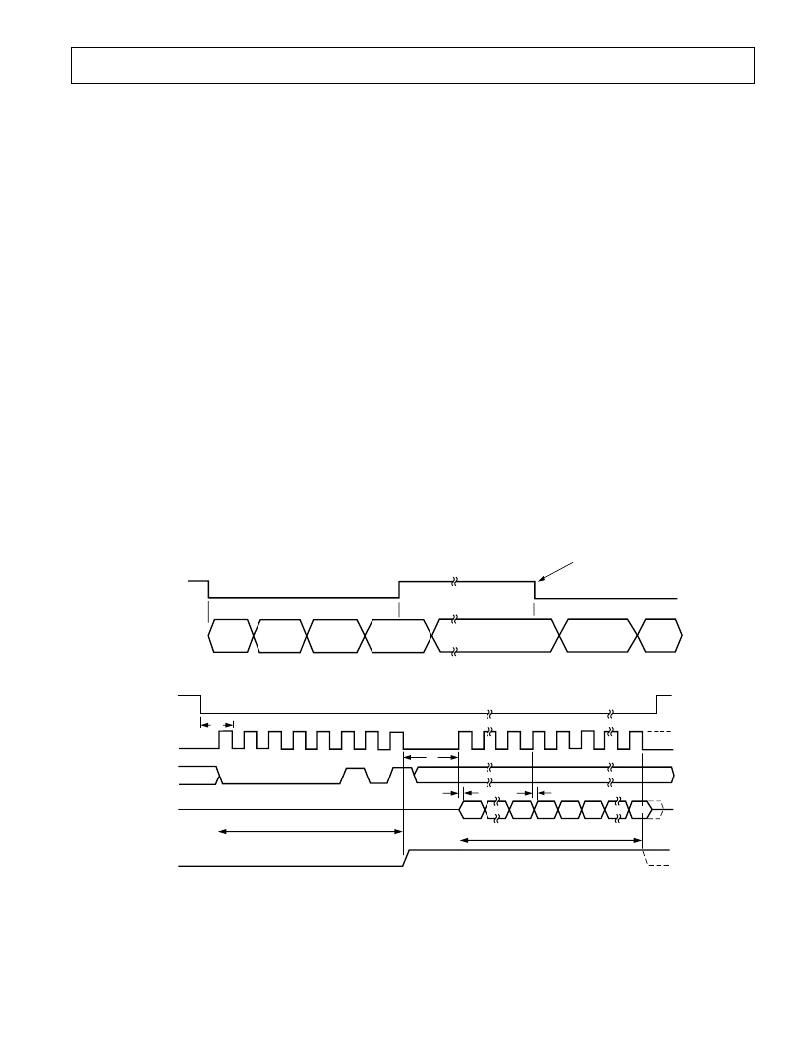
�Interrupt� Timing�
�The� Serial� Interface� section� should� be� reviewed� first,� before� the�
�Interrupt� Timing� section.� As� previously� described,� when� the�
�IRQ� output� goes� low,� the� MCU� ISR� must� read� the� interrupt�
�status� register� to� determine� the� source� of� the� interrupt.� When�
�reading� the� status� register� contents,� the� IRQ� output� is� set� high�
�on� the� last� falling� edge� of� SCLK� of� the� first� byte� transfer� (read�
�interrupt� status� register� command).� The� IRQ� output� is� held�
�high� until� the� last� bit� of� the� next� 8-bit� transfer� is� shifted� out�
�(interrupt� status� register� contents)—see� Figure� 18.� If� an� inter-�
�rupt� is� pending� at� this� time,� the� IRQ� output� will� go� low� again.� If�
�no� interrupt� is� pending,� the� IRQ� output� will� stay� high.�
�interrupt� on� the� MCU.� On� detection� of� the� negative� edge,� the�
�MCU�
�INTERRUPT�
�t� 1�
�t� 2�
�t� 3�
�FLAG� SET�
�IRQ�
�MCU�
�PROGRAM�
�SEQUENCE�
�JUMP�
�TO�
�ISR�
�GLOBAL�
�INTERRUPT�
�MASK� SET�
�CLEAR� MCU�
�INTERRUPT�
�FLAG�
�READ�
�STATUS� WITH�
�RESET� (05h)�
�ISR� ACTION�
�(BASED� ON�
�STATUS� CONTENTS)�
�ISR� RETURN�
�GLOBAL� INTERRUPT�
�MASK� RESET�
�JUMP�
�TO�
�ISR�
�Figure� 17.� Interrupt� Management�
�CS�
�t� 1�
�SCLK�
�t� 9�
�DIN�
�0�
�0�
�0�
�0�
�0�
�1�
�0�
�1�
�t� 11�
�t� 11�
�DOUT�
�DB7�
�DB0�
�READ� STATUS� REGISTER� COMMAND�
�STATUS� REGISTER� CONTENTS�
�IRQ�
�Figure� 18.� Interrupt� Timing�
�REV.� A�
�–15� –�
�相关PDF资料 |
PDF描述 |
|---|---|
| LTC1704BEGN#PBF | IC REG DL BUCK/LINEAR 16-SSOP |
| EEM06DTMI-S189 | CONN EDGECARD 12POS R/A .156 SLD |
| ECM08DCTI | CONN EDGECARD 16POS DIP .156 SLD |
| CS5464-ISZR | IC ENERGY METERING 1PHASE 28SSOP |
| ISL6610AIBZ-T | IC MOSFET DRVR DUAL SYNC 14-SOIC |
相关代理商/技术参数 |
参数描述 |
|---|---|
| ADE7760 | 制造商:AD 制造商全称:Analog Devices 功能描述:Energy Metering IC with On-Chip Fault Detection |
| ADE7760ARS | 制造商:Analog Devices 功能描述:Energy Measurement 20-Pin SSOP 制造商:Analog Devices 功能描述:ENERGY METER IC W/ ONCHIP FAULT & OSCIL. - Rail/Tube |
| ADE7760ARSRL | 制造商:Analog Devices 功能描述:Energy Measurement 20-Pin SSOP T/R 制造商:Analog Devices 功能描述:ENERGY METER IC W/ONCHIP FAULT & OSCIL. - Tape and Reel |
| ADE7761 | 制造商:AD 制造商全称:Analog Devices 功能描述:Energy Metering IC with On-Chip Fault and Missing Neutral Detection |
| ADE7761A | 制造商:AD 制造商全称:Analog Devices 功能描述:Energy Metering IC with On-Chip Fault and Missing Neutral Detection |
发布紧急采购,3分钟左右您将得到回复。