- 您现在的位置:买卖IC网 > PDF目录11486 > ADG739BRUZ-REEL7 (Analog Devices Inc)IC MUX/DEMUX DUAL 4X1 16TSSOP PDF资料下载
参数资料
| 型号: | ADG739BRUZ-REEL7 |
| 厂商: | Analog Devices Inc |
| 文件页数: | 9/20页 |
| 文件大小: | 0K |
| 描述: | IC MUX/DEMUX DUAL 4X1 16TSSOP |
| 产品培训模块: | Switch Fundamentals |
| 标准包装: | 1,000 |
| 功能: | 多路复用器/多路分解器 |
| 电路: | 2 x 4:1 |
| 导通状态电阻: | 4.5 欧姆 |
| 电压电源: | 单电源 |
| 电压 - 电源,单路/双路(±): | 2.7 V ~ 5.5 V |
| 电流 - 电源: | 10µA |
| 工作温度: | -40°C ~ 85°C |
| 安装类型: | 表面贴装 |
| 封装/外壳: | 16-TSSOP(0.173",4.40mm 宽) |
| 供应商设备封装: | 16-TSSOP |
| 包装: | 带卷 (TR) |
| 其它名称: | ADG739BRUZ-REEL7-ND ADG739BRUZ-REEL7TR |
Data Sheet
ADG738/ADG739
Rev. A | Page 17 of 20
APPLICATIONS INFORMATION
EXPAND THE NUMBER OF SELECTABLE SERIAL
DEVICES USING AN ADG739
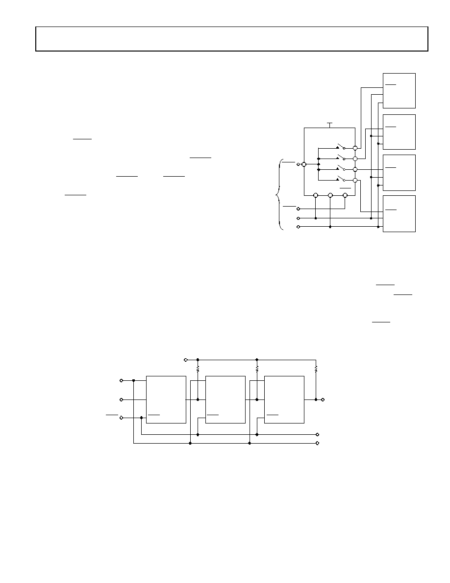
The dual 4-channel ADG739 multiplexer can be used to
multiplex a single chip select line to provide chip selects for
up to four devices on the SPI bus. Figure 30 illustrates the
ADG739 in such a typical configuration. All devices receive
the same serial clock and serial data, but only one device
receives the SYNC signal at any one time. The ADG739 is a
serially controlled device also. One bit programmable pin of
the microcontroller is used to enable the ADG739 via SYNC2,
while another bit programmable pin is used as the chip select
for the other serial devices, SYNC1. Driving SYNC2 low enables
changes to be made to the addressed serial devices. By
bringing SYNC1 low, the selected serial device hanging from
the SPI bus is enabled and data will be clocked into its input
shift register on the falling edges of SCLK. The convenient
design of the matrix switch allows for different combinations of
the four serial devices to be addressed at any one time. If more
devices need to be addressed via one chip select line, the
ADG738 is an 8-channel device and would allow further
expansion of the chip select scheme. There may be some digital
feedthrough from the digital input lines because SCLK and DIN
are permanently connected to each device. Using a burst clock
minimizes the effects of digital feedthrough on the analog
channels.
Figure 30. Addressing Multiple Serial Devices Using an ADG739
DAISY-CHAINING MULTIPLE ADG738S
A number of ADG738 matrix switches may be daisy-chained
simply by using the DOUT pin. DOUT is an open-drain output
that should be pulled to the supply with an external resistor.
Figure 31 shows a typical implementation. The SYNC pin of
all three parts in the example are tied together. When SYNC
is brought low, the input shift registers of all parts are enabled,
data is written to the parts via DIN, and clocked through the
shift registers. When the transfer is complete, SYNC is brought
high and all switches are updated simultaneously. Further shift
registers may be added in series.
Figure 31. Multiple ADG739 Devices in a Daisy-Chained Configuration
DA
1/2 OF
ADG739
VDD
SCLK
DIN
SYNC
S1A
S2A
S3A
S4A
SYNC1
DIN
SCLK
DIN
SCLK
DIN
SCLK
DIN
SCLK
DIN
SCLK
ADG739
ADG738
OTHER SPI
DEVICE
SYNC2
FROM
MICRO-
CONTROLLER
OR DSP
OTHER SPI
DEVICE
SYNC
10758-
023
SCLK
DIN
DOUT
ADG739
SCLK
DIN
ADG739
SCLK
DIN
T
U
O
D
T
U
O
D
SCLK
DIN
TO OTHER
SERIAL DEVICES
ADG739
VDD
R
SYNC
10758-
024
相关PDF资料 |
PDF描述 |
|---|---|
| DSPIC33FJ12MC201-E/SS | IC DSPIC MCU/DSP 12K 20SSOP |
| VE-B3T-IY-B1 | CONVERTER MOD DC/DC 6.5V 50W |
| DSPIC33FJ12MC201-I/SO | IC DSPIC MCU/DSP 12K 20SOIC |
| ADG658YCPZ | IC MULTIPLEXER 8X1 16LFCSP |
| DSPIC33FJ12GP201-E/SO | IC DSPIC MCU/DSP 12K 18SOIC |
相关代理商/技术参数 |
参数描述 |
|---|---|
| ADG741 | 制造商:AD 制造商全称:Analog Devices 功能描述:CMOS Low Voltage 2ohm SPST Switches in SC70 Packages |
| ADG741BKS | 制造商:AD 制造商全称:Analog Devices 功能描述:CMOS Low Voltage 2ohm SPST Switches in SC70 Packages |
| ADG741BKS-R2 | 制造商:Analog Devices 功能描述: 制造商:Rochester Electronics LLC 功能描述: |
| ADG741BKS-REEL | 制造商:Rochester Electronics LLC 功能描述: 制造商:Analog Devices 功能描述: |
| adg741bks-reel7 | 制造商:Rochester Electronics LLC 功能描述: 制造商:Analog Devices 功能描述: |
发布紧急采购,3分钟左右您将得到回复。